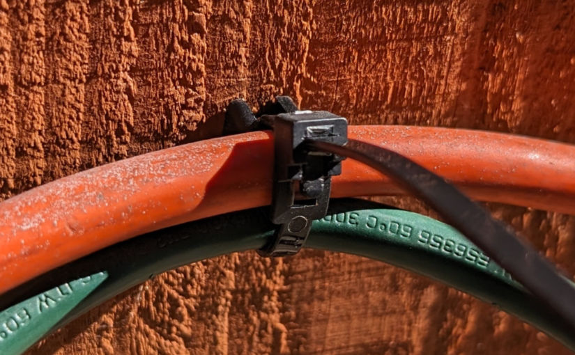
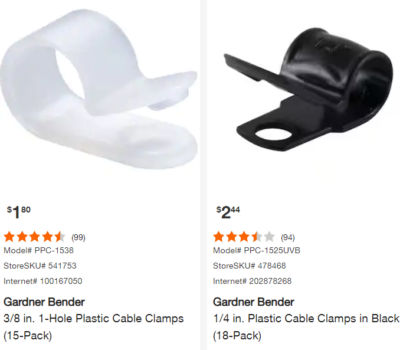
If you need to fasten a cable to a wall, you might be tempted to use a plastic cable clamp like one of these.
These are fine if you need to fasten just one cable to an interior wall. If you need to fasten a cable outside where it can be exposed to the sun or if you need to fasten multiple cables, then these plastic clamps won’t work. The sun will make them crack. What you can do instead is use zip ties with a zip tie base. There are even releasable zip ties.
Releasable zip ties
You can find zip tie base mounts with 4.5mm openings and 9mm openings to accommodate zip ties of different widths.
Zip tie base mount
Just screw the base mount to a wall.
Slide a zip tie through the opening.
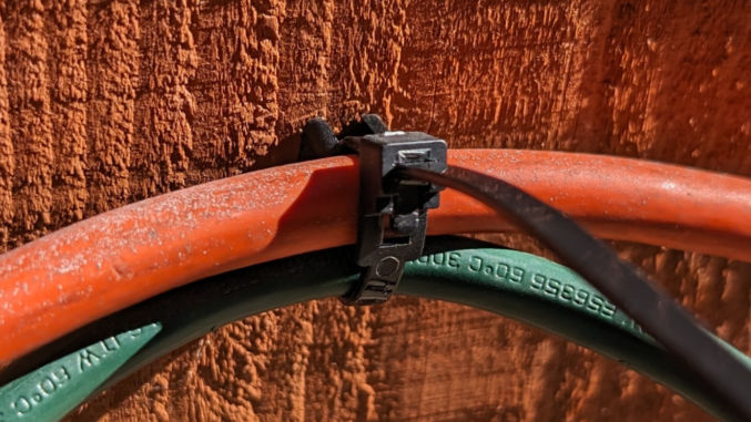
and fasten some cables. Trim the zip tie if desired.
The cables will be tight, and the zip ties should last longer than those flimsy plastic cable clamps.
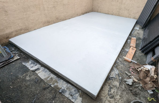
I recently added a slab of concrete in the backyard of one of my rentals. Unfortunately, I made some mistakes along the way. Specifically,
I removed too much dirt from the area where the slab would go
I could have paid less for a contractor to do the concrete work
I should have verified the quality of the contractor’s work
Preparing the Foundation
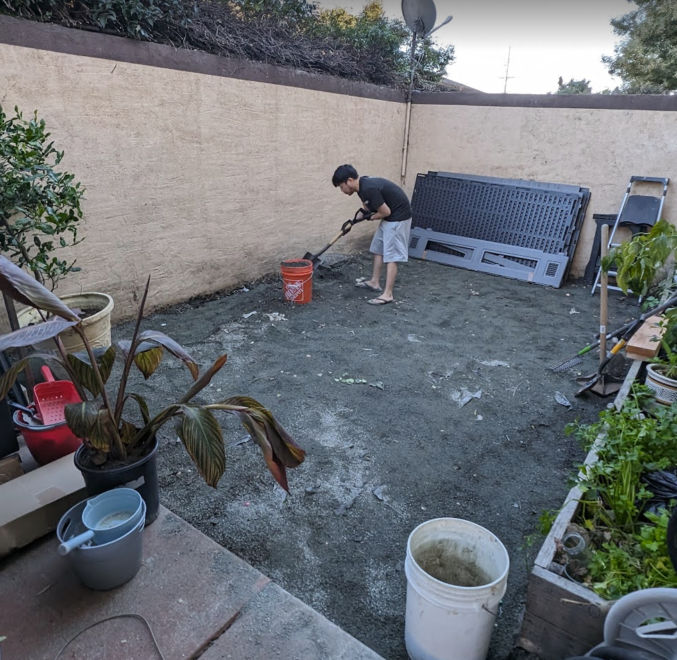
We first removed a lot of dirt and gravel by scooping it into some buckets. We did this so the 3.5″-thick concrete slab would be level with the existing concrete slab.
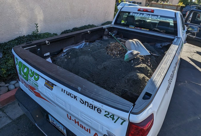
I rented a pick-up truck from U-haul and put tarp on the truck bed to protect it. This also made cleanup easier because I could pull the tarp off the truck along with any remaining dirt on it.
Driving with a full load of dirt made the truck swerve slightly at higher speeds so we took local roads to go to the city dump.
At the dump, we just shoveled the dirt onto the ground. The problem was the cost to dump dirt and gravel. If I had paid by weight, the cost would have been about $500. The clerk instead calculated the cost by volume, which lowered the cost to $372.
After making one trip, I regrettably thought I needed to remove more dirt and gravel. So, we made another trip and I spent another $372. After creating the wood form for the concrete slab, we realized that we had removed too much dirt, which meant I needed 2.5 times the amount of concrete I should have needed.
Getting Quotes
I called around to get quotes from concrete contractors. The slab dimensions would be 9′ x 15.5′ (140 sq ft). The first contractor quoted me $2000, but then lowered it to $1700. He quoted me without seeing the work area.
The second contractor came to see the work area and then quoted me $1500. That meant his rate was $1500/140 = $10.71 / sqft. According to one source, the cost in the California Bay Area to install a concrete slab including materials and delivery is between $8 to $14 / sqft. Therefore, I went and chose the 2nd contractor and paid $10.71 / sq ft.
Creating the Concrete Slab Form
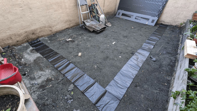
The contractor came and created the wood form. I first compacted the soil using a hand tamper and put down some pond liner where the edge of the concrete would be. Half of the pond liner would be under the concrete. The other half would be under rocks or mulch. The reason for doing this is so that weeds don’t grow along the edge. I left a 30″ gap between the old concrete slab and the new one for rainwater to drain into the ground.
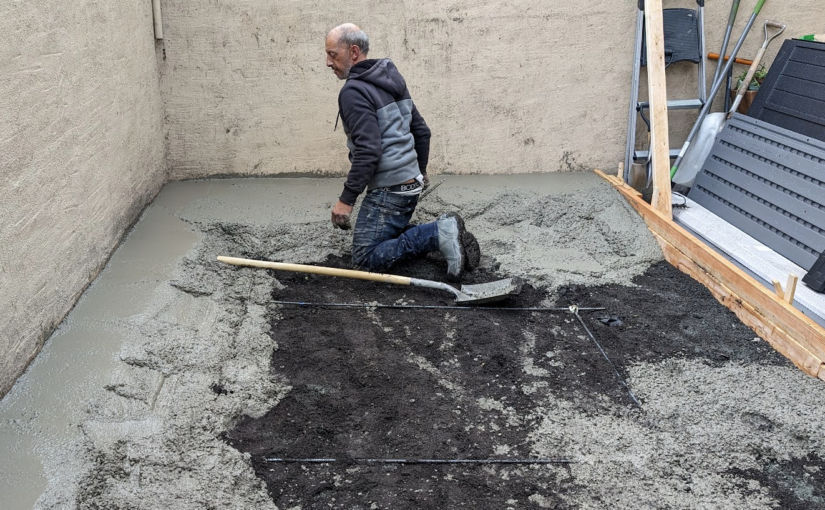
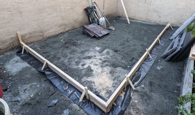
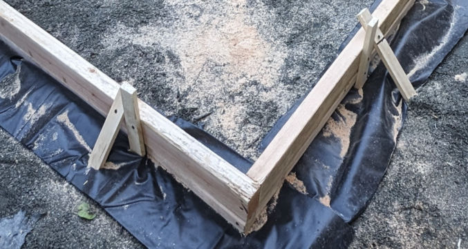
This is when I realized that I had removed too much dirt and gravel. I wanted the top of the new concrete slab to be level with the existing concrete slab in the backyard. Using a level, the contractor drove a wood stake into the ground and marked on it where the top of the 2×4 wood form would go. Screws were screwed through the vertical stakes into the 2x4s. Wood stakes were also used at an angle. This was necessary because without them, the weight of the concrete could push the vertical stakes and cause a deformity in the form. As you can see in the photo below, too much dirt and gravel had been removed, so the contractor had to put another 2×4 below the first set of 2x4s. This resulted in a slab thickness that was approximately 3.5″ x 2 = 7″ (one 2×4 is actually 1.5″ x 3.5″). That’s twice as much as is needed for a standard slab and therefore twice the amount of concrete would be needed.
Furthermore, I wanted the slab to slightly slope towards the long edge so that rainwater could flow into the ground rather than puddle on the slab and weaken it (concrete is porous). To determine the slope, the contractor used a level on the 2×4 and tilted it slightly before screwing it into the wood stakes. Then, he used a red chalk string to snap a line on the wall, marking the desired height of the slab along the wall. Since the red chalk wasn’t clear, he went over parts of it with a black marker as shown below.
Lay Rebar
To reinforce the concrete, the contractor added rebar. He cut the rebar with a reciprocating saw and metal blade.
They then tied the rebar together in what appeared to be plastic-coated wires or electrical (romex) cable.
Pour Concrete
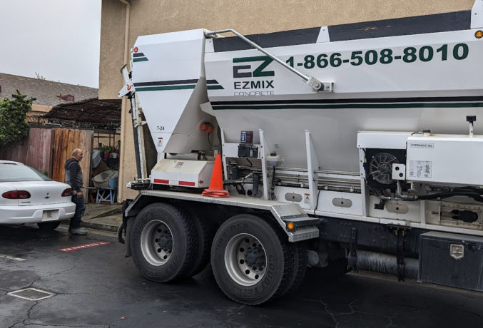
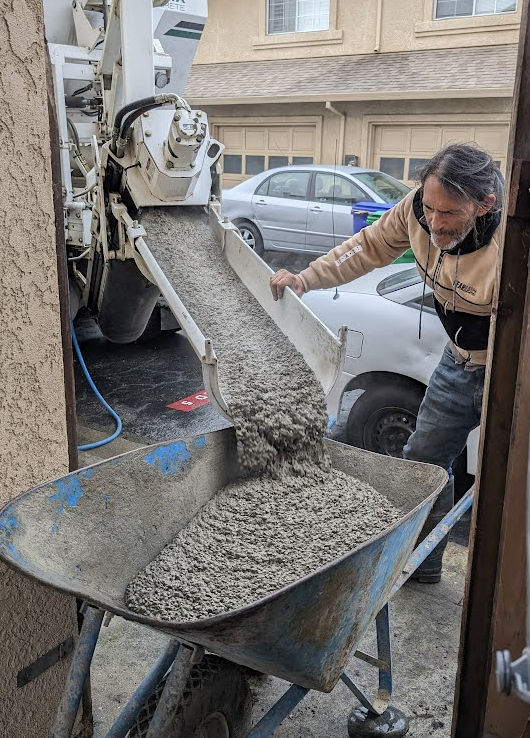
Instead of buying a bunch of bags of concrete and mixing them with water, the contractor ordered a truck to come and deliver premixed concrete.
The premixed concrete flowed down a channel into a wheelbarrow.
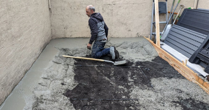
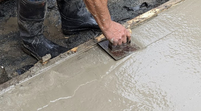
One person transferred the concrete to the work area while the other used a trowel to trowel the concrete.
Occasionally, they’d pull the rebar up so that it would settle in the middle of the slab rather than at the bottom.
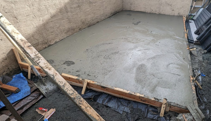
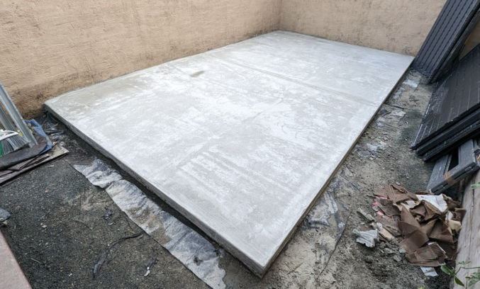
After pouring all the concrete and moving it into place using a hand trowel, this is how it looked.
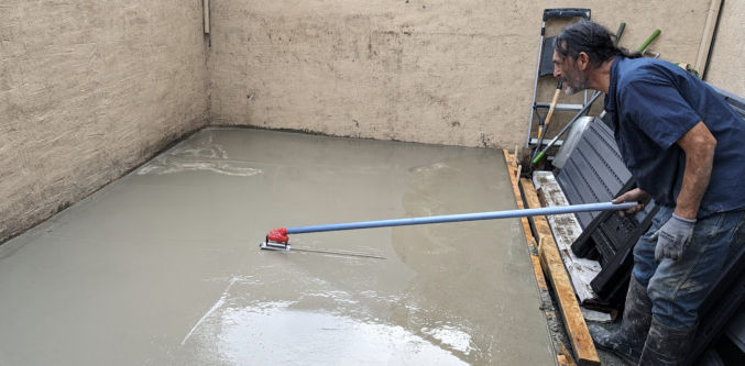
The contractor then used a float attached to a pole to create a smooth surface. If necessary, he would spray a mist of water to soften the concrete.
On the truck, the concrete supplier could see how much concrete was supplied. As you can see below, I needed a total volume of 2.66 cubic yards. People in the business would just say “yards”, which makes no sense since that’s a measure of length rather than volume. What they really mean is cubic yards.
The unit cost of concrete is $169 / cu yd (cubic yard). Fortunately, the concrete supplier put down 2.5 cu yds rather than 2.66 cu yds to save me a little money. Had I not removed so much dirt and gravel, I could have only needed 1 cu yd for a 3.5″ thick slab. Instead, the resulting slab is now 6 to 6.5″ thick.
For small loads, the concrete supplier charges an extra $80 for 1 to 2.75 cu yds or $60 for 3 to 4.75 cu yds. Again, the supplier gave me a small discount by only charging me an extra $60 instead of $80. Then, there’s the delivery fee, which costs $80. The total cost for just the concrete was $607.91.
For comparison, if you buy bags of concrete at Home Depot, transport it yourself, and mix it with water, you’d pay $612.80 + 10% tax = $674 for the same 2.66 cu yds (72 cu feet) of concrete.
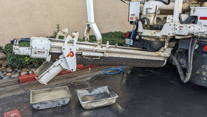
The concrete supplier cleaned his truck and washed the surrounding area.
The contractor then used an edging trowel to create a rounded edge.
He also used a special tool to create a control joint line.
Once the concrete dries a bit, he’ll give the concrete surface a brushed texture so it’s not slippery smooth. Then, tomorrow, he’ll remove the wood form.
Smoothen Uneven Spots
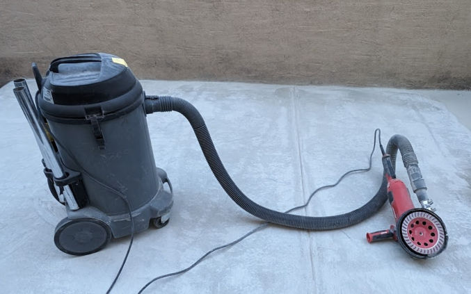
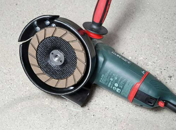
Unfortunately, the contractor didn’t do a good job. There were some uneven areas that drove me crazy. To fix this, I used a 7″ concrete grinder.
7″ Dust Shroud I bought the Dustless Technologies 7 in. Universal Dust Shroud Pro for Angle Grinders from Home Depot. It’s a bit expensive, but it works better than others I’ve tried.
N95 Face Mask and/or Neck Gaiter and/or Balaclava Despite using a powerful shop vac, some dust will still escape. Wear an N95 face mask like this one coupled with a neck gaiter or a balaclava.
Rubber Strip and Hose Clamps To prevent the shop vac hose from detaching from the angle grinder, I wrapped a 2″-wide rubber strip around the connection and clamped it using two hose clamps.
Knee pads You will be on your knees when grinding concrete. Wear knee pads. I like this one on Amazon.
IMPORTANT: concrete dust is very dangerous if inhaled! Always wear protection.
N95 maskN95 mask with neck gaiter for added protectionN95 face mask and balaclava for even better protection
When grinding concrete, move relatively quickly and in a circular motion to avoid creating uneven spots.
Etch the Surface
Raw concrete doesn’t look that great. To beautify it, I’ll apply some epoxy to it. In order for the epoxy to stick, the smooth surface needs to be etched. The easiest way to do this is by renting a flooring tool with the Diamabrush concrete prep attachment. In my case, the surface wasn’t smooth, so I was able to skip this step.
Apply Epoxy
Since cars will not go on my slab, I’ll apply some 1-part epoxy. I like this one in silver gray:
Before applying epoxyAfter applying epoxy (it was still wet)
Lessons Learned
For some reason, it costs more to dispose of dirt and gravel at the dump than it is to be supplied the same amount of premixed concrete, including delivery.
Before removing dirt, create the wood form first so you’ll know how much dirt to remove. The concrete slab need only be 3.5″ thick.
Since I paid $608 for the concrete, assuming the other materials (2×4 lumber and wood stakes) cost $42 (conservative estimate), then that means I paid the contractors (2 people) $1500 – $608 – $42 = $850 for pretty much one day of actual work. So, each contractor got $425 a day or $425 / 5 hours = $85 an hour. That’s a high hourly rate. However, all concrete contractors charge a high rate even though the number of hours worked is low. Next time I’ll ask for a quote for the labor only since now I know the costs for the materials.
The quality of the contractor’s work was poor. There were uneven spots and the concrete was mostly level rather than slightly sloping in one direction for water runoff. There was also one lower area where water would puddle. Next time, verify the quality of the contractor’s work.
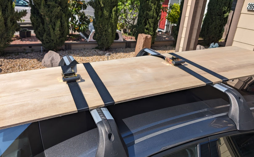
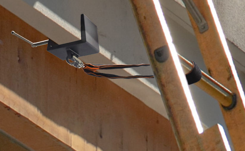
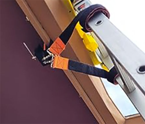
The way it works is you clamp the clamp onto your eaves, secure the hooks to the hole on the clamp, then wrap the straps around your ladder, securing it using the hook and loop velcro.
It’s a simple idea, but the price is $90. It just went on sale for $56, but that still seems overpriced. Not sure why Harbor Freight hasn’t created a cheaper alternative.
Anyway, you can probably make your own for much less by just using
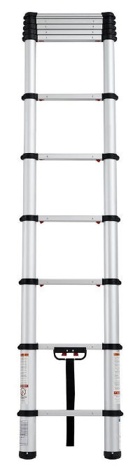
For an easy-to-transport ladder, this telescoping ladder ($160) is great.
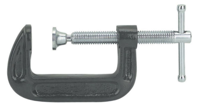
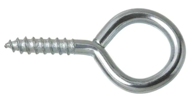
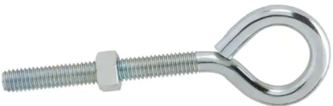
If you need this for your own home and there is one spot you would always use to get on the roof, and if you want a more secure solution, replace the C-clamp with a large screw eye or eye bolt with nut and use the ratchet straps instead of the cam buckle strap.
screw eyeeye bolt with nutI just used one cam buckle strap.
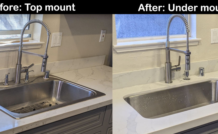
The old sink was the top-mount kind. Water kept leaking behind the sink into the base cabinet.
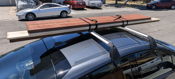
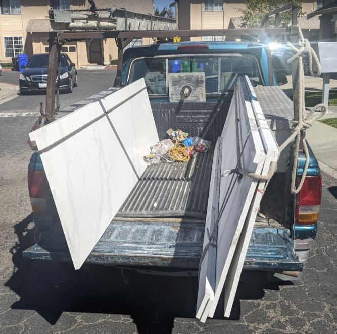
The same quartz countertop was on sale from $500 to $400 (8-foot-long slab).
Found a Mexican guy in the parking lot and got him to transport and install the countertop.
The slab was leaning against the side of the truck and secured using a rope.
To remove the old countertop, I placed a towel on top of it and hit it with a sledgehammer to break it up into small pieces without pieces flying everything.
It actually didn’t take long to remove the old countertop.
I then unscrewed the old plywood and threw it away.
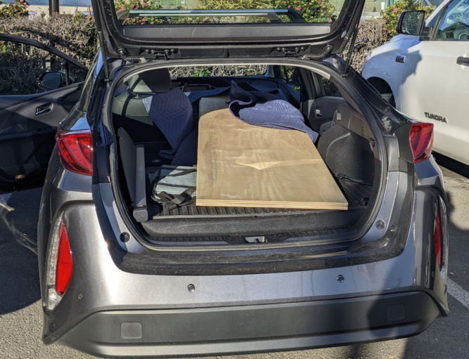
For an undermount sink, you need at least 19/32″ thick plywood. I had Home Depot cut a 4×8′ plywood sheet in have to make two 2×8′ sheets.
I was able to fit both 2×8′ sheets in my car 🙂
I screwed the plywood into the base drawers. There was moisture damage and a hole in the wall which I had to fix.
I patched up the hole and smoothened the wall surface.
That 19/32″ thick plywood should be strong enough for the undermount sink.
I found an 18-gauge undermount sink (30″ x 18″ x 9″ deep) at HD Supply for $175.
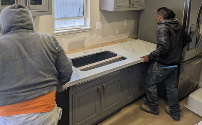
The installers cut a hole in the plywood for the sink. They should have used a jigsaw to make the hole.
They cut the countertop outside because it produces a lot of dust.
First, they cut the slab to length. Water was needed to keep the blade from getting too hot and keep dust from going everywhere.
Here, he’s cutting the hole for the sink using an angle grinder. I think he should have used a circular saw to make a straighter cut.
He then polished the edges while his assistant squirted water.
The sink didn’t come with a paper template for cutting a hole in the plywood and countertop. An easy way to mark an outline where to cut the whole is by turning the sink over, sticking your hand into the drain hole, and using a pencil, mark the perimeter.
I had them drill 3 holes: one for the faucet, one for a soap dispenser, and one for the dishwasher.
They put extra strong construction adhesive along the perimeter of the sink hole where the sink lip will sit. They also put it on the plywood in various places to secure the countertop to the plywood.
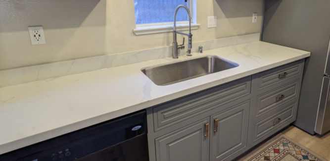
They then glued the backsplash to the wall and applied silicon to the joint.
When smoothening out silicone or caulk, you should always use a tool like the Husky 3-in-1 caulk tool. The triangular edge makes for a perfect finish.
When installing the p trap, I chose the flexible kind that you can cut to length. It’s much easier than fooling around with metal or PVC drain parts and it never leaks.
The information below is primarily for California. However, much of it still applies nationwide.
Interesting Fact
The sun essentially provides an endless supply of energy. In fact, with the amount of sunlight that hits the earth in 90 minutes, we could supply the entire world with electricity for a year — all we have to do is catch it!
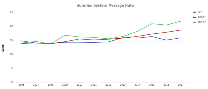
Seattle had the lowest price of any major metro area at $0.118 per kWh while San Diego, Houston, Urban Hawaii, and San Francisco all had electricity rates above $0.311 per kWh.
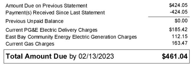
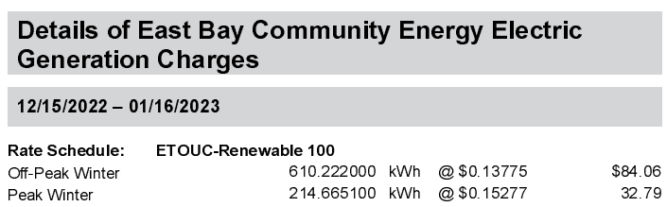
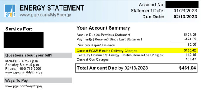
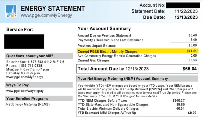
In January 2023, my PG&E energy bill was $461.04. The electricity portion alone was about $300. Looking at the bill below, the electricity portion is divided into two:
Delivery charges: This is the cost PG&E charges to just deliver electricity to my house.
Generation charges: This is the cost to generate electricity, e.g. by solar, wind, etc.
The delivery rate averages $0.38 / kWh.
The generation rate averages $0.14 / kWh.
The cost to deliver electricity is way more than the cost to generate it. Adding the two rates up, we get $0.38 + $0.14 = $0.52 / kWh.
According to the California Energy Commission, 66.4% of California’s energy comes from non-renewable sources and 33.6% comes from renewable sources. 14.2% comes from solar.
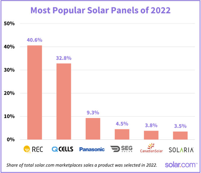
There are nearly 50 REC models and 80 Q CELLS models available through the solar.com network, ranging in wattage from 265W to 450W (although 400W is now considered the norm, and anything under 365W is considered rare).
REC and Q CELLS back their panels with a 25 year product warranty.
Best solar panels manufactured in the US
BRAND – HQ LOCATION
PANEL
MANUFACTURE LOCATION
WHY SOLAR.COM LIKES IT
Silfab – Canada
SIL Mono series
Bellingham, Washington
Durable, >20% efficient
Q Cells – Korea
Q. Peak Duo Series
Dalton, Georgia
Durable, >20% efficient
Mission Solar – US
MSE PERC series
San Antonio, Texas
Qualifies for Buy American Act
Solaria – US
Power XT series
Fremont, California
>20% efficient, superior shade performance
Best solar panels made overseas by US-based companies
BRAND – HQ LOCATION
PANEL
WHY SOLAR.COM LIKES IT
Sunpower – San Jose, CA
A-series
Up to 22.8% efficiency, 25-year warranty, built-in AC inverter
Sunpower – San Jose, CA
X-Series
Up to 22,7% efficient, extremely low degradation rate, 25-year warranty
SEG – Pleasanton, CA
SEG-410-BMD-HV
21.25% efficiency, 25-year warranty
Aptos Solar – Santa Clara, CA
DNA-120-MF26-370W
20.29% efficiency, durable, 30-year warranty
Top 3 solar panels by degration rate
PANEL
DEGRADATION RATE
PERFORMANCE WARRANTY
SunPower X-Series
0.2% to 0.25% per year
92% of minimum peak power after 25 years
Panasonic EverVolt® Photovoltaic series (EVPV)
No more than 0.25% per year
92% of maximum power after 25 years
REC Alpha series
No more than 0.25% per year
92% of nameplate power output after 25 years
Best solar panels for efficiency
Residential solar panels typically range between 15% and 20%, with the industry leading panels pushing 23%.
MANUFACTURER
MODEL
EFFICIENCY RATING
SunPower
A-series
Up to 22.8%
SunPower
X-series
Up to 22.7%
Panasonic
EverVolt® Photovoltaic series
Up to 22.2%
SunPower
M-series
Up to 22%
REC
Alpha series
Up to 21.9%
Silfab
Elite series
Up to 21.4%
SEG
SIV AC Module Series
Up to 21.25%
Silfab
X series
Up to 21.1%
Solar World
Sunmodule series
Up to 21.1%
S-Energy
SL40-60MCI-370
21.04%
Solar Panel Efficiency
There are a number of factors that influence solar panel efficiency. They include:
Temperature — Solar panels operate best in temperatures between 59 and 95 degrees Fahrenheit
Solar panels still generate electricity on cloudy days, although not as effectively as sunny days. Solar panels can capture both direct and indirect light (light that shines through clouds), but perform at around 10-25% of their normal efficiency when it’s cloudy.
Cloudy days can be beneficial, however, as rain washes the panels and increases their overall efficiency.
Color
If you’ll have solar panels that are visible, e.g. from the street, you may want to pick ones that look good. Most solar panel frames are anodized aluminum and come in silver or black. Choosing a black frame can enhance the look of your system greatly. You may be interested in getting “all black” panels, where the frame, backsheet, and cells are all the same black color.
Inverters
Most inverters have warranties ranging from anywhere between 5 and 10 years, though some can be extended to 25 years.
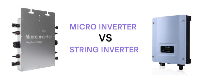
There are 2 types of inverters.
String inverter
Pros
Lowest cost
Standard inverter
Performs well with no shade
Cons
Overall production decreases if one panel is damaged or shaded
No ability to monitor each panel individually
Not optimal if your solar panels are facing different ways
Increasing power needs are more difficult and may require second central inverter installation
Microinverter
Pros
Shade from a nearby tree won’t reduce the whole solar panel system power output
Individual panel monitoring available
Increasing power needs are easier and less expensive than installing a second central inverter
Good for rooftops where solar panels may face different directions
Cons
Higher initial cost
Not necessary if all panels face the same way and are not shaded
Power Optimizers
Power optimizers can optimize the power before sending it to a central string inverter.
Pros
More efficient than string inverters
Less expensive than micro-inverters
Individual panel monitoring available
Cons
Higher initial cost
Not necessary if all panels face the same way and are not shaded
Solar Inverter Efficiency
Peak (max) efficiency and weighted (average) efficiency
Clipping/Scalping
If the solar panel DC output exceeds the max power rating of the inverter, the excess power is clipped (wasted).
It’s normal for the DC system size to be about 1.2x greater than the inverter system’s max AC power rating. For example, a 12 kW solar PV array paired with a 10 kW inverter is said to have a DC:AC ratio — or “Inverter Load Ratio” — of 1.2.
Solar Monitoring System
In order to ensure your solar system is producing energy normally, it’s important to make sure your solar panels are paired with an energy production monitoring system.
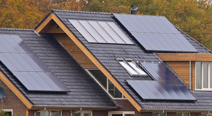
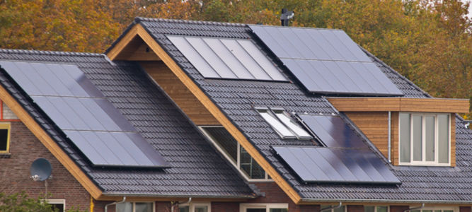
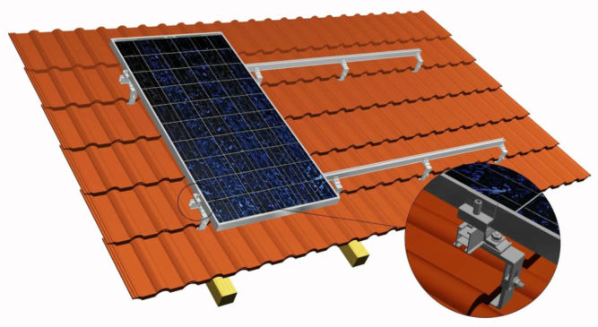
Solar Mounting and Racking System
It’s important to make sure your racking system, if roof-mounted, is properly flashed and sealed to ensure your roof is well-protected against the elements.
Roof Type
Roof Material
Note
Composite shingles
Most common roof material. Easy and cheap to install solar panels on them.
Clay Tiles
More expensive to install than all other roof types.
Concrete Tiles
Cheaper to install than clay tile roofs but more expensive than shingles.
Metal Standing Seam
Easy and cheap to install.
Tar and Gravel
More expensive to install than clay tiles.
Wood
Not recommended for installing solar panels
Warranties
Most major solar manufacturers including REC, SunPower, and Panasonic offer warranties that guarantee a certain level of output over 25 years, and some companies are beginning to offer 30-year warranties. The performance warranty guarantees that a panel’s output capacity will not drop by more than 0.7% per year, or less than 20% over 25 years.
Solar panels don’t disappear when they reach the end of their warranty, their production capacity just slowly degrades over time.
Solar Equation
The average energy needs of a U.S. household is a 6.62-kW solar system to match the 9,000 kWh of average energy usage by U.S. households each year. And, the typical solar panel makes 320 watts of electricity in ideal sunny conditions. Here’s how many solar panels that equals.
Divide 6.62 kW (the system size) by .320 kW (the wattage per panel) = 20.69—rounded up that’s 21 panels. While your home is far from average, this is how you can calculate your own rough estimate.
Solar Panel Wattage VS Efficiency
Solar panels are rated based on the watts they generate. The higher the wattage rating, the greater amount of power your solar installation will produce. Most residential solar panels have power output ratings from 250 to 400 watts, depending on panel size and how well they convert sunlight into energy. While higher power ratings are considered preferable, power output is not the sole factor in judging a solar panel’s performance.
For instance, two solar panels may each have a 15% efficiency rating, yet the power output rating of one is 250 watts and the other is 300 watts.4 The higher output may simply be due to the 300 watt panel’s larger physical size–rather than having a high efficiency or more advanced technology. Therefore, panel efficiency is a better indicator of solar panel performance than just power output for meeting your energy needs.
Incentives
The solar investment tax credit (ITC) is a 30% tax credit that you are allowed to claim in the form of a deduction from your income taxes (after any available rebates) off the overall gross system cost, including any necessary upgrades to the main panel box upgrades in order to go solar.
In August 2022, the Inflation Reduction Act increased the tax credit from 26% to 30% and extended it until 2032. It also renamed it the Residential Clean Energy Credit (although most people still call it the ITC or solar tax credit).
So if you purchased a solar system worth $25,000 in 2022, you can claim a $7,500 deduction on your 2022 taxes that you file in early 2023.
The new and improved solar tax credit also applies to battery storage, whether or not it’s connected to solar. So you can claim the tax credit for adding battery storage to an existing solar system or for battery storage that’s not connected to solar at all.
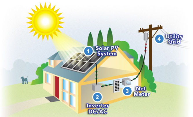
Net Energy Metering (NEM) is the policy that allows you to push and pull energy to and from the grid through your electrical meter. Traditional utility users pull energy from the main grid, use the energy in their home, and the meter counts how much is used. With solar, you will push your excess energy into the grid during the day and pull it out at night to use for lights, TV, A/Cm or anything else you may need. The grid functions as a bank storing your energy from your solar panels until you are ready to use it. With a battery backup system and secure power supply, you can use the energy from your system when the grid goes down.
Net Energy Metering Credits
If you don’t use all the energy your system produces in a day, that energy will roll over to the next day and so on. This happens day after day, month after month. This allows you to use all the energy you produce with your solar system. If you have higher usage months (AC, guests, holidays, etc) you draw from the extra energy credits you earned earlier in the year.
Solar True-Up
Once a year you “true up” with your utility where you settle the balance on your energy credit. If you consume more than you produce then you’ll pay the utility for the excess energy you pulled from the grid. If you produce more energy than you consume, the utility will compensate you for your excess energy at a below-retail rate.
NEM 1.0, 2.0 and 3.0
In most cases, 1 kWh of electricity pushed onto the grid offsets 1 kWh of electricity pulled off the grid.
However, energy utilities are making a nationwide push to weaken net metering by paying less than retail prices for solar exports. Most notably, California’s NEM 3.0 reduces the export rates by over 75%.
NEM 3.0 Final Decision: The California Public Utilities Commission (CPUC) unanimously voted to approve NEM 3.0. Under NEM 3.0, customers of PG&E, SCE, and SDG&E with solar systems will receive an average of 8 cents per kWh for the excess power they push onto the grid. This is roughly 75% less than the average export rate of 30 cents per kWh under NEM 2.0. IOU customers have until April 13, 2023 to grandfather a new solar system into NEM 2.0 by submitting a complete interconnection application.
NEM 3.0 key takeaways:
Current solar owners will remain under their existing net metering policy
Solar owners under NEM 3.0 will earn around 75% less for the excess electricity they push onto the grid
Under NEM 3.0, the payback period for solar and battery storage systems will be roughly equal to the payback period of solar only systems
Californians can be grandfathered into NEM 2.0 by submitting an Interconnection Application for a new solar system by April 13, 2023
Payback period and savings under NEM 2.0 vs NEM 3.0
Scenario 1: Cash purchase of an average 7.6 kW system with 100% offset
SOLAR UNDER NEM 2.0
SOLAR UNDER NEM 3.0
Monthly energy bill (previously $250)
$18
$96
Payback period
4.6 years
6.5 years
Lifetime savings
$116,680
$73,620
Scenario 2: 12-year loan for an average 7.6 kW system with 100% offset
SOLAR UNDER NEM 2.0
SOLAR UNDER NEM 3.0
Monthly energy bill (previously $250)
$162
$239
Down payment
$0
$0
Lifetime Savings
$110,308
$67,248
Scenario 2: 20-year loan for an average 7.6 kW system with 100% offset
There are two steps required to grandfather a solar system into NEM 2.0.
Submit a solar interconnection application to your utility before April 13, 2023
Install and receive permission to operate (PTO) within three years of submitting your interconnection application
Quick Note: NEM 3.0 is not retroactive. Existing solar systems will remain under their current net metering policy for 20 years from their interconnection date.
According to the final NEM 3.0 proposal, a valid solar interconnection application includes:
Complete application
Signed contract
Single-line diagram
CSLB Disclosure Document
Signed consumer protection guide
Oversizing attestations (if applicable)
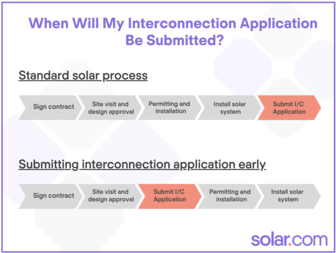
Typically, solar installers submit the interconnection application after the system has been installed. However, in response to NEM 3.0, many – but not all – companies are changing their operations process to submit as early as possible.
Since solar installations typically take 3-5 months to line up, it’s important to find an installer that has changed their process to submit interconnection applications early.
Beginning in January, you should be able to get emailed proof that you have been grandfathered within 2-3 weeks of signing the contract.
A 10-year study concluding in 2015 by the Lawrence Berkeley National Laboratory found that solar panels add around $4 per watt of capacity installed – or $4,000 per kW. Here’s how that adds up based on the size of your system:
SOLAR SYSTEM SIZE
INCREASE TO HOME VALUE FROM SOLAR PANELS*
4 kW
$16,000
5 kW
$20,000
6 kW
$24,000
8 kW
$32,000
10 kW
$40,000
Solar Installation Company
Factors to consider when choosing an installation company are
their number of installations,
their locations,
their bankability,
their online reviews,
their certification,
length of their workmanship warranty covering
roofing penetrations,
water damage,
electrical work, and
anything related to their installation for the time period described
Possess at least one year of installation experience
Solar Panel Maintenance
Solar PV systems require almost zero maintenance. Be wary of these ‘maintenance packages’ as they are often overpriced.
System Size
To determine the size of your solar system and the number of panels you’ll need, you need to know how much electricity you use on average per day.
Looking at my PG&E electricity usage and cost over the last 12 months below, we find that my average monthly electricity usage was 527 kWh. But, since I bought a plug-in hybrid and started charging my car in October, I’ll take my average to be from the last 3 months, which is 709 kWh. Of course, the last 3 months of the year were cold and daylight ended early at around 5 PM, so my electricity usage went up for other reasons as well. We’ll assume my average monthly electricity needs is 700 kWh and my annual usage would be 700 x 12 = 8400 kWh / year.
Start Date
End Date
kWh
Cost
Note
2022-01-18
2022-02-15
656.84
$168.47
2022-02-16
2022-03-17
577.84
$134.91
2022-03-18
2022-04-18
494.57
$102.54
2022-04-19
2022-05-17
358.42
$68.48
2022-05-18
2022-06-15
372.67
$82.26
2022-06-16
2022-07-17
443.17
$110.39
2022-07-18
2022-08-16
416.57
$103.91
2022-08-17
2022-09-15
452.3
$115.19
2022-09-16
2022-10-16
420.99
$94.50
2022-10-17
2022-11-15
604.61
$136.73
Includes charging EV
2022-11-16
2022-12-14
695.44
$162.45
Includes charging EV
2022-12-15
2023-01-16
824.89
$185.42
Includes charging EV
Average
Last 12 months
527 kWh
$122
Average
Last 3 months
709 kWh
$161
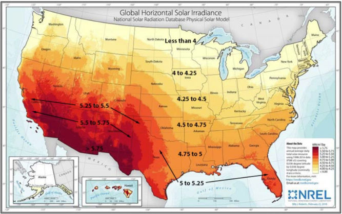
To continue this analysis, we’ll need the peak sunlight hours where I live. According to the map below, my peak sun hours is 5.
A
Monthly electricity usage
700 kWh / month
B
Daily electricity usage
24 kWh / day
A/30
C
Hourly electricity usage (kWh)
1 kWh / hour
B/24
E
Solar panel system output needed per day
5 kWh / day
F * peak sun hours (5)
So, the solar panel system size I would need is a 5 kW system. But, since solar panels don’t operate at maximum efficiency 24 hours a day, we’ll add a cushion of 25%. That brings the system size to 5 kW x 1.25 = 6.25 kW.
The average solar panel produces 400 W. So, the number of panels I would need is 6250 / 400 = 15.6 panels.
For a 6 kW size, I was quoted $25,820. If I apply the 30% federal tax credit, I’d get $7,746, which brings the effective cost to $18,074. Since the minimum lifetime of the solar system is 25 hours, then we can calculate the cost per kWh as $18,074 / 25 years / 365 days / 24 hours = $0.08 / kWh. That’s a lot cheaper than my current electricity rate of $0.52 / kWh (PG&E generation + delivery rate).
Since my monthly electricity needs are 700 kWh. Then we can compare costs as follows:
Cost / month
Cost / 25 years
Solar with 30% tax credit
700 kWh * $0.08
$56
$16,800
Grid
700 kWh * $52
$364
$109,200
As you can see, going solar saves a ton of money. And that doesn’t even include the rising cost of electricity from the grid, which averages 2.2% per year.
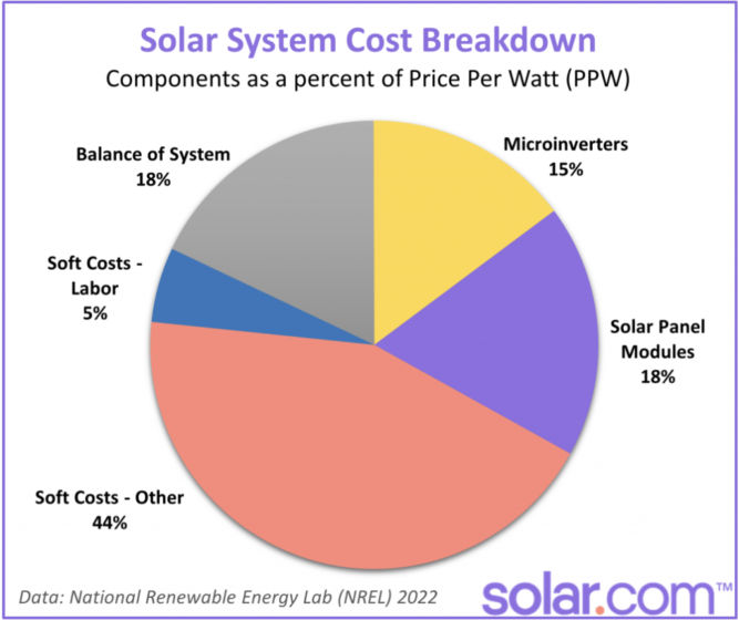
Cost Breakdown
Loans
“Same as cash” option
This means that the lender will fund the full amount of the loan, but only collect payments based on 70% of the outstanding balance during the first year or so. This amounts to a 30% discount on your payments for the first 12-18 months and makes Day One savings greater than on a traditional loan.
After the 12-18 months is over, the homeowner is expected to pay down the loan balance by the amount of the tax credit.
In the example used earlier, the homeowner would receive a $20,000 loan but only pay interest on $14,000. If at the end of the 12 month grace period the homeowner fails to pay back the tax credit amount, then the lender will start charging interest on the $6,000 portion from that point forward.
Combo Loan
Combo loans are independently financed. There are two separate loans.
The first loan is for 70% of the contract price, which has an interest rate (for which the homeowner qualifies). The second loan covers the remaining 30% of the contract price.
This second loan is meant to equal the federal tax credit amount and typically lasts for 18 months with 0% interest. If this amount is not paid off in that allotted time frame, the balance adopts the same APR as the first loan, whatever that may be.
Some lenders tout extremely low nominal rates (some as low as 1.89%). They don’t tell you is that there is something known as a ‘dealer fee’ that can run as high as 17%.
Make sure you check the following:
True APR
Monthly payments
No dealer fees
No prepayment penalty
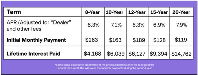
Loan Term
The table below compares monthly payments and lifetime interest paid for a $20,000 loan at different terms and APRs.
The most popular loan with Solar.com customers has a 12-year term, no pre-payment penalties, and interest rates of 2.99-4.99% depending on your credit score. The 12-year term is common because for most customers, their monthly loan payment is equal to or less than their current utility bill.
Sun Exposure
The more sun your solar panels get, the more money they can save you.
Comparison Shopping Checklist
Solar Panel
Brand
Type
Number of panels
Wattage per panel
Efficiency
Color
Warranty (fine print)
Company bankability
Solar System
Size (kW)
energy monitoring system
All-inclusive total cost (permits, materials, warranties, taxes, financing costs, etc)
Inverter
Type
Max power input
Peak efficiency
Weighted efficiency
Warranty (fine print)
Installation Company
number of installations,
their locations,
their bankability,
their online reviews,
their certification (NABCEP),
length of their workmanship warranty covering
roofing penetrations,
water damage,
electrical work, and
anything related to their installation for the time period described
do they guarantee minimum daily energy production?
NEM 2.0 Grandfathering
Is the company prepared to submit the documents needed for NEM 2 grandfathering early in the process?
Loan
Length of loan
True APR
Monthly payments
No dealer fees
No prepayment penalty
Update
After installing solar panels, my electricity bill has gone down significantly.
It’s January 9, 2023, and it’s cold here in California. Sure, it’s nothing compared to the freezing temperatures in other parts of the country, but still, it can get pretty chilly in the evening and early morning.
And as the temperature drops, my energy bill goes in the opposite direction.
On top of that, high inflation has made everything, including energy, even more expensive.
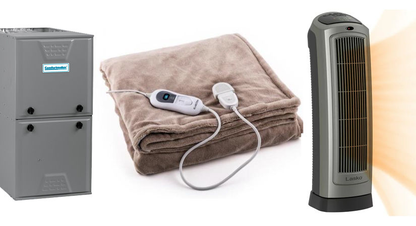
Despite having an energy-efficient gas furnace, using it to heat up a 1600-square-foot house still seems more expensive than it should be. Plus, even if heating the entire house was inexpensive, it seems wasteful since many parts of the house are not always actively used. Though I have a gas furnace, according to EnergySage, the average wattage of an electric furnace is 10,000 to 50,000 watts. For comparison, my space heater uses 1500 watts. That makes sense since it plugs into a 120V / 15A outlet, which can support a maximum of 1800 watts before tripping the circuit breaker. And for another comparison, I have an electric throw (62″ x 50″ Microplush Electric Throw Blanket Leopard/Black – Biddeford Blankets) that, according to the label, uses 130 watts. A king-size electric blanket will use up to 200 watts. Personally, I actually find the electric throw more comfortable than the space heater and central furnace when I’m stationary (watching a movie or sleeping).
Electric blanket
130 – 200 watts
Space heater
1500 – 1800 watts
Electric furnace
10,000 to 50,000 watts
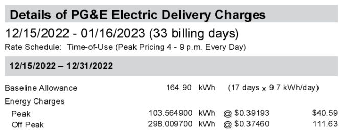
According to my PG&E bill, my electricity cost is
Off peak: $0.37460 / kWh (kilowatt hour)
Peak (4-9 PM): 0.39193 / kWh
Assuming I run a 200W electric blanket and an 1500W space heater for 3 hours a day during peak hours, I can find the cost for each using the formula:
W/1000*H*CPKWH
where
W = device watts
H = number of hours
CPKWH = cost per kWh (I’ll choose peak time)
Device
Math
Cost/day
Cost/month
Electric Blanket
200/1000*3*0.39193
$0.23
$7
Space Heater
1500/1000*3*0.39193
$1.76
$53
So, yeah, the electric blanket or throw is way cheaper!
There are many different ways you can edit home improvement videos. Here are some:
Make a Video From Photos
This is pretty simple to do. You can just add a bunch of photos to the video track of your video editor, animate each photo (many video editors can do this automatically), add some music to the music/audio track, and render the video. The result can be pretty good but it doesn’t really give a sense of the amount of effort or process involved. Here’s an example clip.
Regular 1x Speed Video
If you have a short video, leaving the speed at normal 1x speed might be okay. But, if your video is long, people will get bored very quickly. Since most home improvement projects take longer than 30 seconds, I don’t recommend this option, unless you are maybe adding a voiceover that explains what you are doing in the video.
Fast Speed (Timelapse) Video
Another option is to just timelapse the entire video. Some home improvement projects can take all day. Many people, including myself, will just leave a camera somewhere that will take many still photos at a set interval to create a timelapse video. You can also record an entire day’s worth of video, which I’ve also done using a WyzeCam mounted on a wall. Timelapsing an entire video is as easy as speeding up the video clip. The downside is the audio is also sped up and often doesn’t sound good so you usually mute the audio and optionally add some background music. Here’s an example.
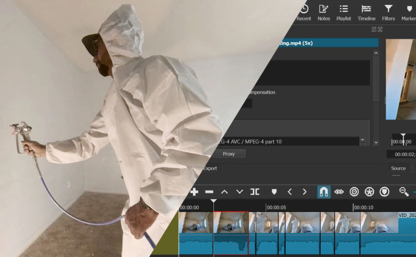
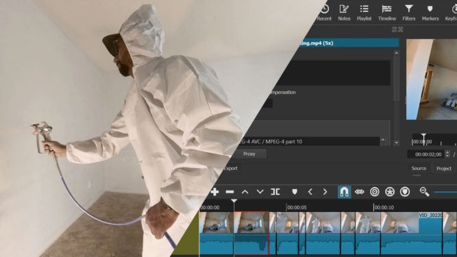
Mixed-Speed Video
Another option is to timelapse (speed up) certain parts of the video and leave the other parts at regular 1x speed. This is definitely more work but I personally find this better than just speeding up the entire video. However, I find the best effect is when the regular speed segments are ones that have a high volume, e.g. when you’re using a tool that makes a lot of noise (drilling, jackhammering, cutting, etc). Here’s an example.
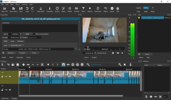
I normally use Corel VideoStudio to edit videos but for this purpose, I find Shotcut to be easier to use. Shotcut, which is free, shows the waveform very clearly, runs faster and hasn’t crashed on me yet. The UI takes some getting used to but once you get the hang of it, it’s pretty simple to us. Here are the steps I follow in Shotcut to create this type of video:
Open the original video in Shotcut
Drag it from the player to the timeline
Zoom in, if necessary, so that you can see the audio waveform
Choose some or all segments where the waveform is high (high volume)
Scrub the playhead until you find a segment where the waveform is high (high volume) and the segment is interesting to show at 1x speed
Split the video at that playhead position.
Move the playhead by where you want to end the segment. For 1x speed segments, I choose a duration of 1 second. You can advance the playhead by 1 second by going to “Player” > “Forward One Second”.
Delete any segments you don’t want to keep (choose Ripple Delete to remove empty space as well)
Click on a segment you want to speed up, click Properties, and change the speed. I choose 5x.
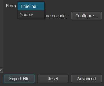
Click the Export button, select “Timeline” in the From field, and click “Export File”.
I changed the speed of this segment to 5x.
Video Showing Only Selection of 1-second Segments
Another option is to create a video from a selection of 1-second segments. Some segments will probably have high volume, e.g. drilling, jackhammering, cutting, etc. , Others may not, e.g. lifting, cleaning, drawing lines, etc. Again, I find this much easier to do in Shotcut than in Corel VideoStudio. Here’s an example.
Here’s how I do it in Shotcut:
Open the original video in Shotcut
Drag it from the player to the timeline
Zoom in, if necessary, so that you can see the audio waveform
Scrub the playhead until you find an interesting segment
Split the video at that position
Move the playhead forward or backward by 1 second (“Player” > “Forward One Second” or “Backward One Second”.)
Split the video again to create a one-second clip
Repeat steps 4-7
Delete all other segments (choose Ripple Delete to remove empty space as well)
Click the Export button, select “Timeline” in the From field, and click “Export File”
I reduced this 3-minute long video to 3 seconds (each segment is 1-second long) where the volume was high.
Merging Clips
If you end up with a bunch of video clips that you want to merge and you don’t need to apply any transitions or effects, you can merge them almost instantly with LosslessCut.
One of my properties is in an HOA. Though many people dislike HOAs and having to pay a monthly HOA fee, one huge benefit of being in an HOA is you never have to deal with unsightly views from the street. If someone violates the CC&Rs, they are fined and forced to stop. This improves everyone’s curb appeal including the neighborhood as a whole. For me, and many others, that’s valuable. But, my other properties are not in an HOA. And, unfortunately, people have very different ideas of what looks good. One neighbor put down pavers himself but was either lazy or didn’t know how to do it right. As a result, the pavers are uneven and weeds are growing everywhere. Another neighbor beheaded their tree leaving a 5′-tall trunk in the middle of their front yard surrounded by probably one of the cheapest rocks you can find – gray gravel. This is bad, but it’s nothing compared to another property of mine where one immediate neighbor is a mechanic who works on cars in his driveway almost 24/7. The neighboring property is a triplex owned by a slumlord who doesn’t appear to care one bit that her ghetto tenants are destroying her property as long as she collects the very low rent that she can get. Their lawn is destroyed because sometimes they park their cars on it. Their garbage bins are always overflowing and are a fly magnet. And if that’s not enough, the other immediate neighbor covered their lawn that meets my property line with concrete and illegally parks a beat-up pickup truck on it. They also leave a grill, used car parts, engine oil, and various other garbage along their side of the property line. As a result, no matter how much I improve my property, being sandwiched between two ugly neighbors significantly ruins my property’s curb appeal. Reporting code violations to the City is useless as they never do anything. Putting up a fence helps but the municipal code limits how tall they can be. Fortunately, there is no height limit on trees as there are 2 and even 3-story-tall trees in nearby front yards. So, one solution I decided on to block the unsightly neighbors is by creating a fence made up of Cypress trees. These trees are super low maintenance, evergreen, the leaves don’t fall and create a mess that you have to clean up all the time, and they grow in a very predictable manner (straight up) so you don’t need to worry about stray branches hitting your eaves or roof.
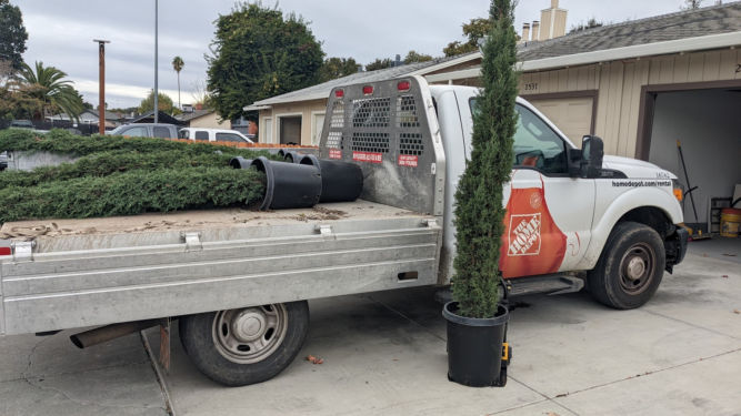
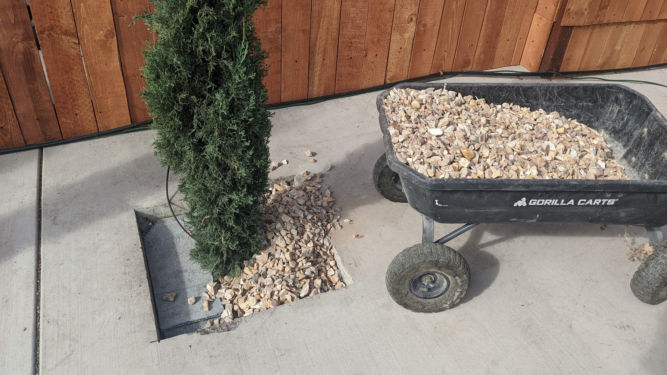
I bought the 5-gallon trees from a nearby nursery for $75 each. In Spring, you can get them at Costco for $40. You can rent a flatbed pickup truck from the Home Depot for $19 for 75 minutes. These trucks are ideal because you can lower the tailgate and the sides as well, making the loading and unloading of trees, or anything for that matter, much easier.
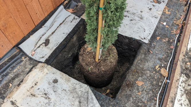
Along the east-facing fence, I had to dig holes in a section where there was no concrete. Digging holes is a PITA for sure. But, using the right tools like a gas-powered auger makes it less of a PITA. In the photo below, I made a square hole by making 4 small holes at each corner using the auger, then another hole in the middle, and then removed the remaining dirt.
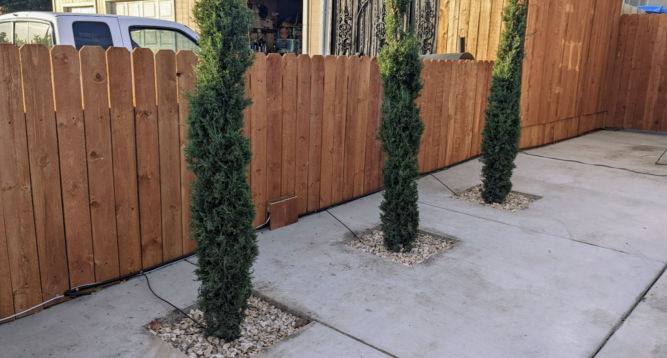
Along the west-facing fence, I had previously poured concrete so I had to cut squares in it for the trees to go in. After backfilling with dirt, I covered the dirt with cement board to be used as weed fabric (regular weed fabric is useless), and then poured a layer of ginger rock.
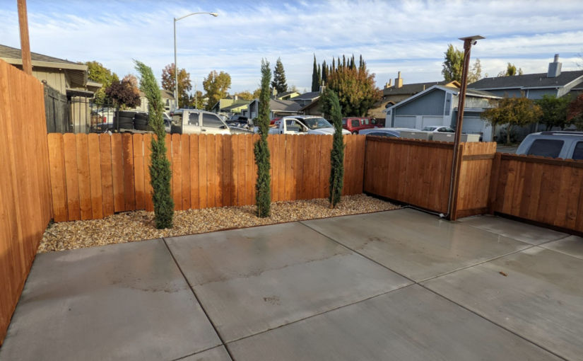
Here’s how the west side looks. The fence boards are red-stained and cost about $3 each from Home Depot. I ran a 1/2″-diameter tube from the back of the building for irrigation. Connected to that tube are smaller tubes for drip irrigation directly at the root of each tree. The photo below is from before the concrete was pressure washed.
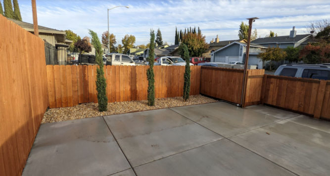
Here’s how the east side looks. You can still see the junk cars next door but after these trees grow tall and thick, my tenants will be shielded from the unsightly views next door and the curb appeal will continue to improve and there will be a clear delineation between my property and the neighboring ugliness.
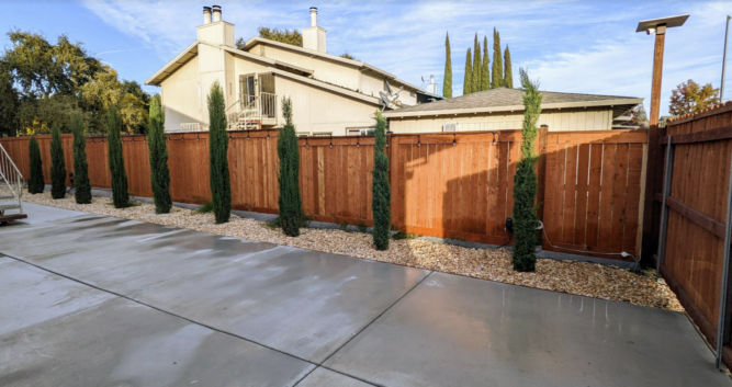
I continued the fence/tree design alone much of the east side to block as much of the neighbors as possible.
Within 5 years, the trees will be as tall as the 2-story buildings and have a much wider diameter.
So there you have it. One way to block trashy neighbors while not violating most municipal codes.
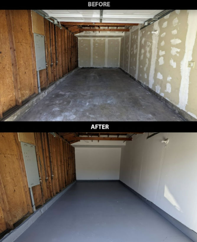
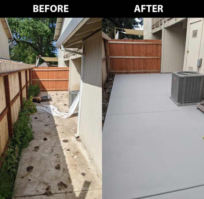
Concrete in your home is everywhere. From your driveway, garage floor, patio, porch, and backyard, everyone has concrete. Unfortunately, concrete is porous and can easily get dirty. Oil, dirt, and stains from all sorts of things can permeate and discolor concrete seemingly permanently. Pressure washing concrete with a high-pressure washer won’t even remove the discoloration. To protect your concrete from stains, you’ll need to seal it. If your concrete is already ugly or if you want to change the way it looks, you’ll need to apply a coating on it, e.g. epoxy. But, in order for any coating to adhere and not peel off, you’ll need to prepare (prep) the surface very well. This is the most important step when renovating concrete. Do it right, and you’ll vastly improve and transform the look of your concrete and your home. Here’s an example before and after picture of a garage floor I renovated.
This is not the step where you want to be lackadaisical. Following are different ways you can prep your concrete surfaces.
Acid
You can pour acid on bare concrete and scrub it around. However, the chemicals are toxic, smelly, and harmful.
Floor Polisher with Diamabrush Concrete Prep Attachment
The concrete prep attachment is for etching bare concrete floors to prepare for adhesive coatings. This option is much better than using acid, IMHO. But, it’s a bit more expensive. I think I rented it for $140 for 4 hours from the Home Depot. It’s a bit tiring to use because the polisher likes to move in one direction so you need to force it to go in the other direction.
Floor polisherDiamabrush concrete prep attachment
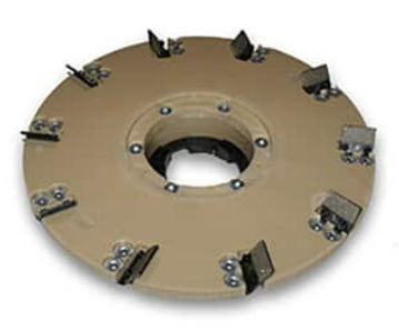
Make sure you choose the concrete prep attachment and not the coating removal attachment picture below. Both look similar but the latter is for removal of mastics, glue, adhesives, thinset epoxies and paint from interior concrete.
Diamabrush coating removal attachment
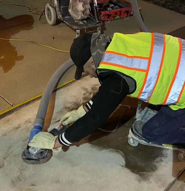
Angle Grinder with Concrete Grinder Attachment and Dush Shroud
Another option is to grind the concrete down. This, however, requires getting down on the ground and can take a long time. You’ll also need to use a shopvac to suction the dust as this will product a ton of dust. Concrete dust is harmful because it contains silica which can mess with your lungs. If you have a small area to grind or if you need to grind edges, this tool is handy.
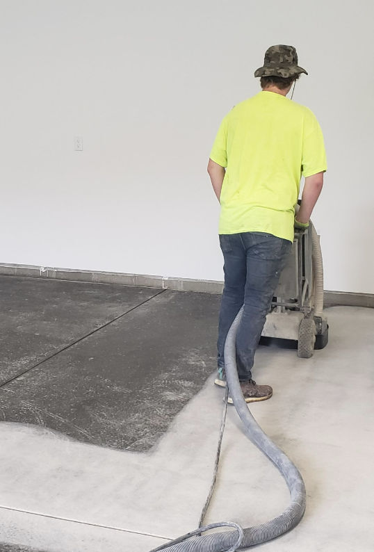
Walk-Behind Concrete Grinder
This commercial-grade concrete grinder can be rented at the Home Depot. It grinds down concrete high spots, removes sealers and thin mil paints, removes mastics and preps floors to accept new coatings.
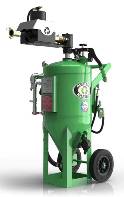
This tool can be rented from Sunbelt Rentals for $270 / day. This tool works by blasting media (shot) at the concrete to scour the surface. This is one of the best ways to prepare concrete. However, what’s annoying about it is you have to periodically pick up the shot media that escapes the tool.