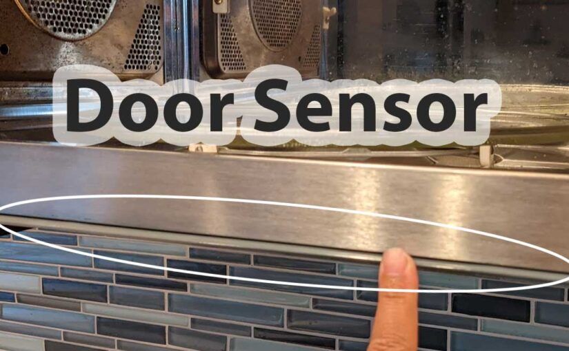
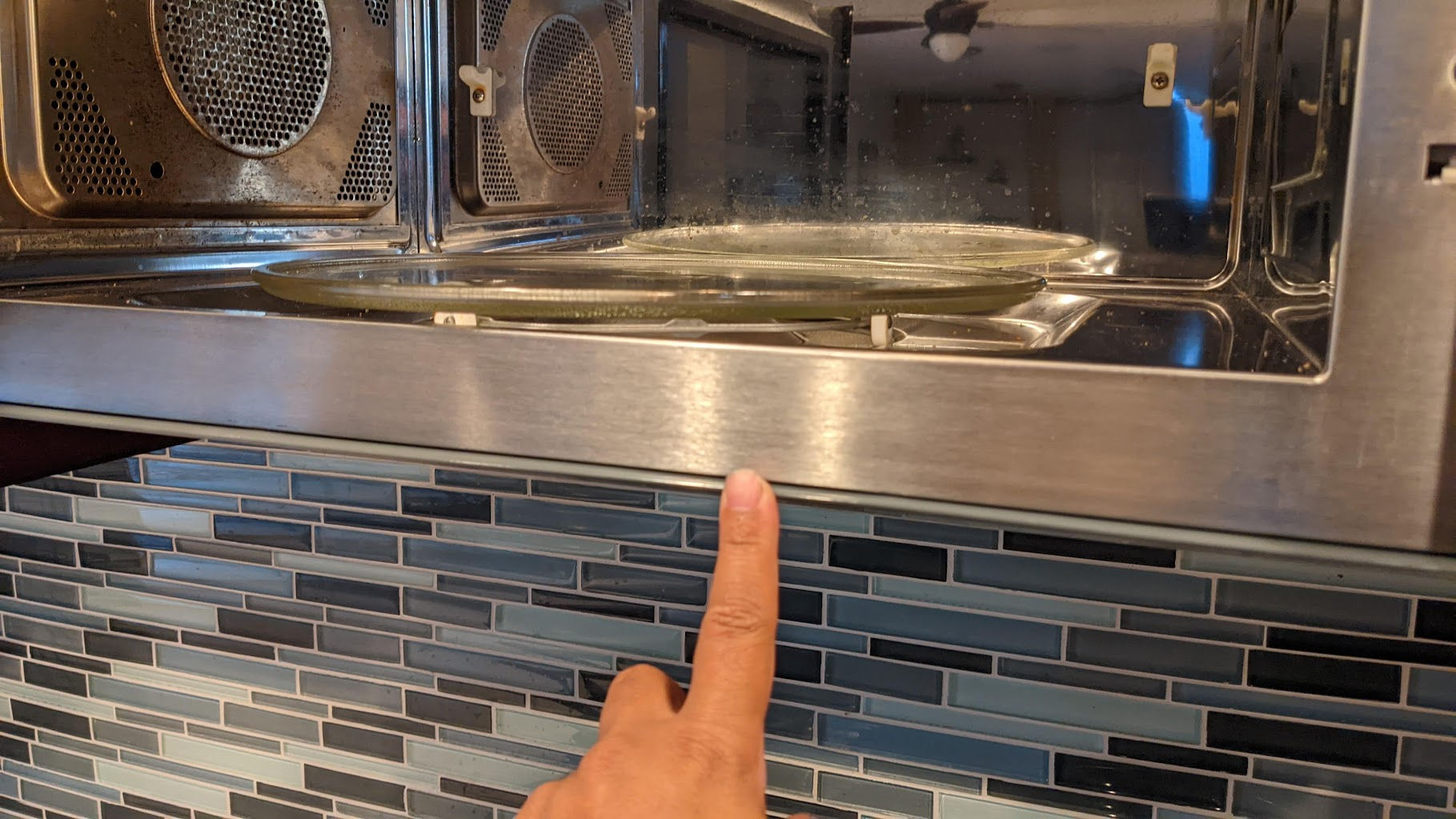
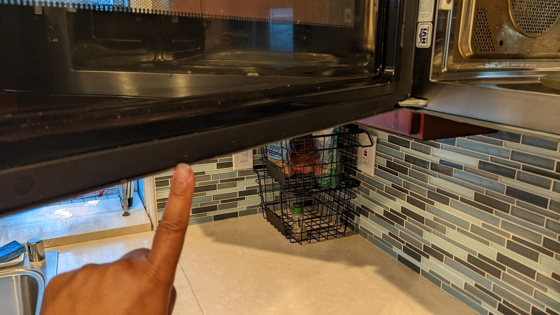
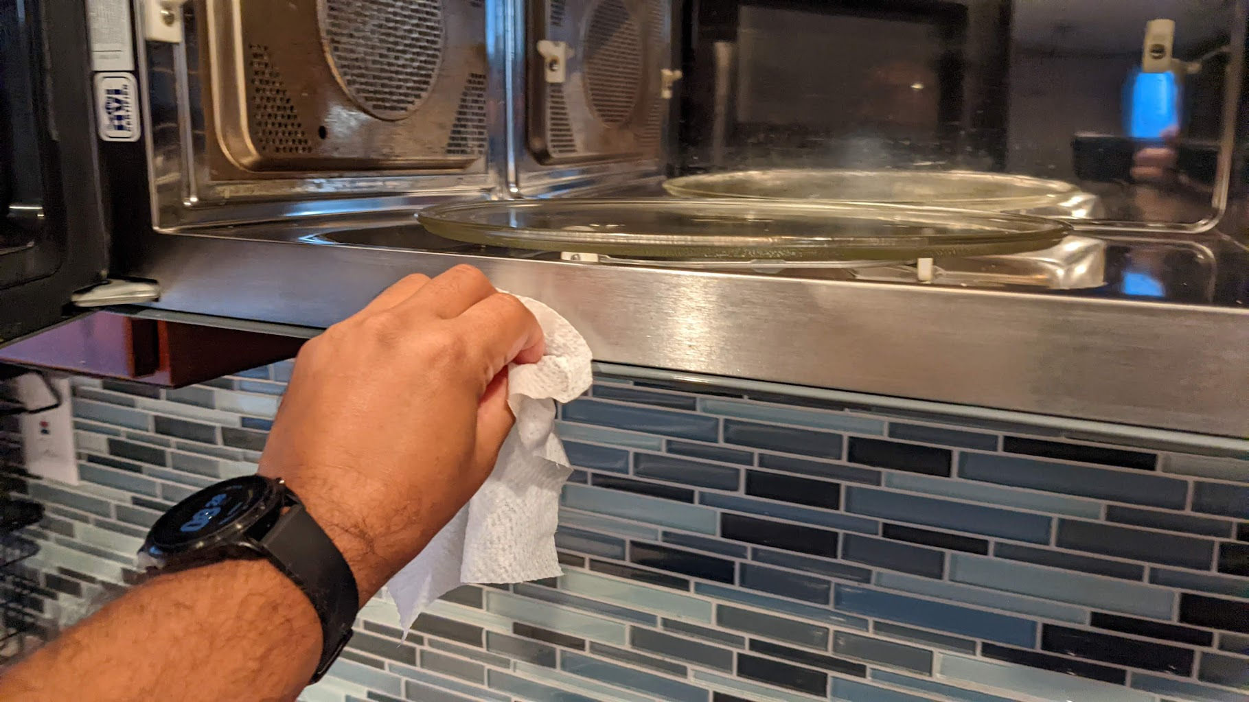
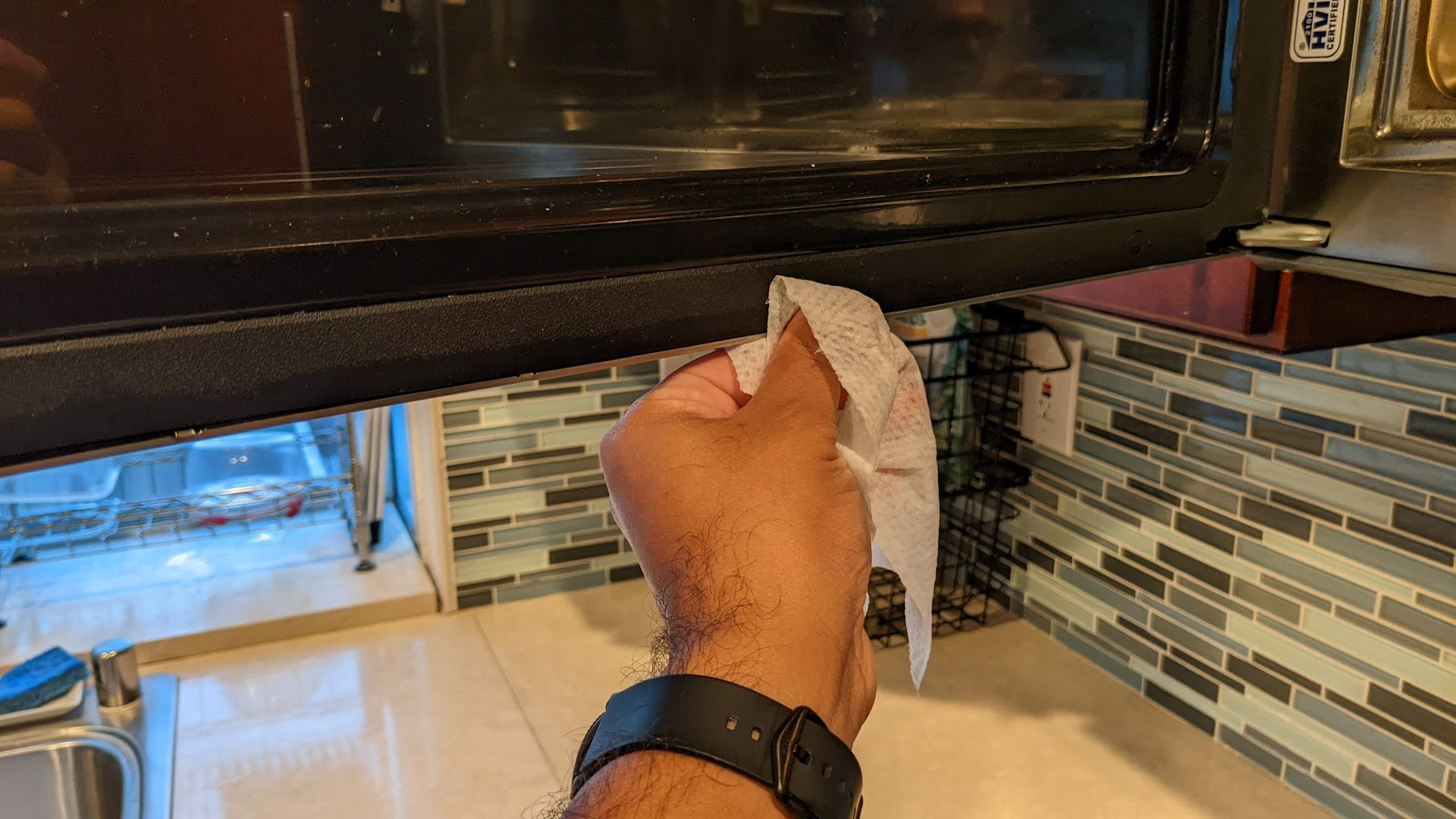
Recently, the microwave would keep giving an error saying I needed to “open / close door” no matter how many times I open and close the door. This prevented me from microwaving anything. Since this was an expensive microwave, I didn’t really want to buy a new one. Fortunately, fixing this error was easy. It turns out that there is a sensor along the inside front bottom edge that detects whether the door is closed or not. I prefer to clean using wet Clorox disinfectant wipes. I find that they lift dirt up easily. I’d then wipe again using a dry paper towel. After doing that, the open/close door error goes away and the microwave can start.
Door sensor along inside bottom edge of microwaveDoor sensor along inside bottom edge of microwave doorCleaning the door sensorCleaning the door sensor
Do a Google search and you’ll find that many people have problems with the ice maker in their Samsung refrigerator. Of all the things Samsung can make, it’s ridiculous that they can’t even make an ice maker that just works without freezing up every 3 months. I have the 28 cu. ft. Food Showcase 4-Door Flex™ Refrigerator with FlexZone™ in Stainless Steel. I went with the counter-depth version. It’s smaller than the full-depth version but more expensive for some reason.
I have no problem with this fridge but as cool as it may look, the ice maker is a joke! I used up my extended warranty to have a “certified” technician come out 3 or 4 times to fix the ice maker (some of them are just clueless!). Anyway, in every situation, the ice maker stopped working because of ice buildup preventing the ice maker from working. One technician (a Samsung technician) said it was because I wasn’t using the original Samsung (overpriced) water filter. So, I put in an overpriced Samsung original water filter and, unsurprisingly, the ice maker still stopped working after a while – again, because of ice buildup. And, of course, I’m past the extended warranty so I have to fix it myself. If your stupid Samsung ice maker stops working because of ice buildup, here’s how you fix it (until it stops working again in 3-6 months).
Buy a steam cleaner
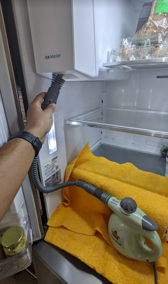
I bought this Bissel steam cleaner on Amazon. It’s supposed to be used for cleaning but it works well for melting ice that jams your stupid Samsung ice maker.
Melt the ice
Put some water in the steamer, wait till it’s hot, then stick the nozzle up the ice maker opening and pull the trigger. Super hot steam will fill up the ice maker box and begin to melt any ice in there.
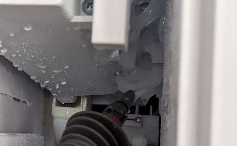
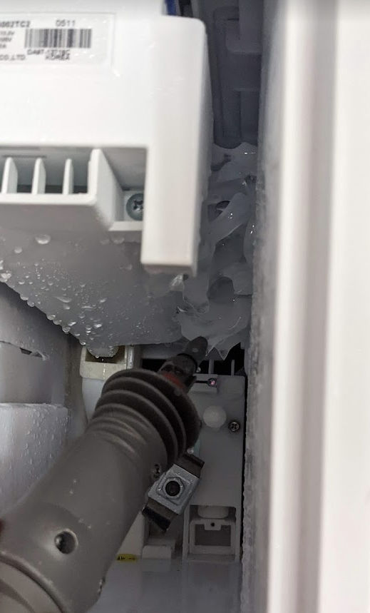
After a while, try to pull out the ice box. If it still doesn’t come out, repeat until it does. Once it comes out, you’ll see some ice buildup like in the picture below.
Use the steamer to target the ice buildup until you can remove all the ice.
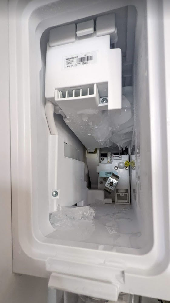
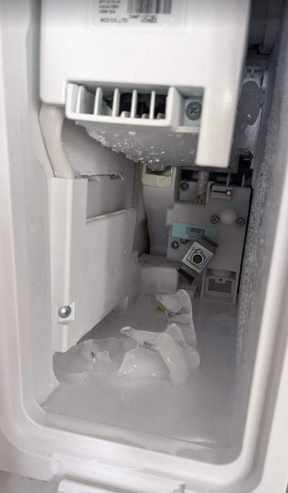
In the picture below, you can see that most of the ice is no longer stuck. Once you’ve removed all the ice, put the ice box back in and wait a day for new ice to be made.
And that’s how you temporarily fix your stupid Samsung ice maker.
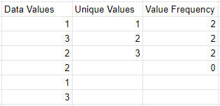
I’m often finding myself needing to calculate the frequency of unique values in a spreadsheet. It turns out it’s a 2-step process. For example, if you have a column of data as shown below and you want to know how many times the numbers 1, 2, and 3 occur, you need to first add a column containing the unique values in column 1. Then, you can use the frequency function to calculate frequency.
1. Get Unique Values
In column 2, get the unique values in column one using the unique function:
=UNIQUE(A2:A7)
If you want, you can also sort the values as follows.
=SORT(UNIQUE(A2:A7))
2. Get Value Frequency
In column 3, get the value frequency using the frequency function. The data is in column 1 and the classes are in column 2.
FREQUENCY(data, classes)
=FREQUENCY(A2:A7, B2:B4)
Google Sheets seems to want to add an extra row with the value 0. I just ignore that.
Note: the tutorial below works using Google Chrome and English subtitles where a user’s language setting in Netflix is set to English. It does not work for other languages like Arabic and Chinese. To download subtitles in those languages, you may need to change your language setting in Netflix.
1. Start playing a Netflix video
This tutorial uses Google Chrome.
2. Open Chrome Inspector
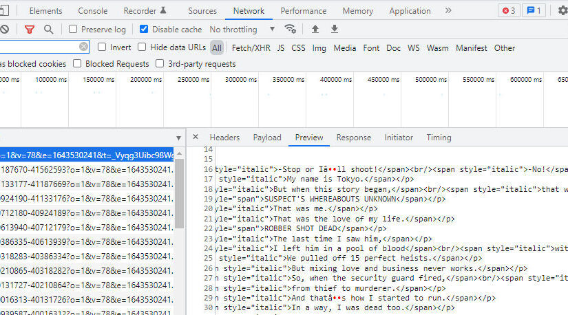
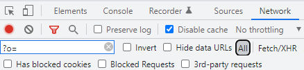
Click CTRL+SHIFT+I to open the Google Chrome Inspector. Click the Network tab. Make sure “All” is selected. Enter “?o=” in the filter field. Make the video window smaller than full screen so you can see both the video window and the Inspector window side by side.
3. Find subtitle file
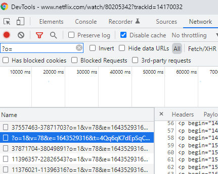
In the Inspector, sort the files by “Name”. If subtitles are turned on, you will see a filename that begins with “?o=”.
If you don’t see the file, then in the video, click to see the subtitle options and then click on a subtitle, e.g. “English”. You should then see the subtitle file appear in the list of files in the Inspector.
4. Download subtitle file
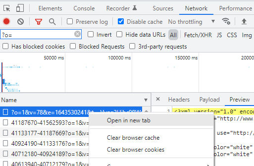
In the Inspector, right-click on the file and click “Open in a new tab” to download the file. Rename the file to something like english-subtitles.xml.
5. Convert subtitles to SRT format
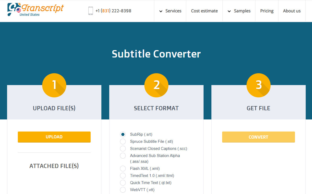
The XML format of the subtitles may not be user-friendly. You can convert it to SRT format by going to https://gotranscript.com/subtitle-converter where you can convert the format for free.
If you have multiple subtitles, e.g. in different languages, you can merge them using this online tool.
If you’d like to edit subtitles, you can try this free online editor. Some of the nice features are
clean user-friendly interface
can load a video from a YouTube URL
can change video playback speed
when you click on a subtitle, the video automatically jumps to the timestamp of that subtitle
When drawing rectangles, you can specify length & width by separating the measurements with a comma. For example: to draw a two foot by four foot rectangle, you can enter 2', 4' into the measurement box. The order of the measurements matches the order of the axes (R, G, B). For example: Red, then Green; Red, then Blue; or Green, then Blue.
When items are pre-selected, you can click anywhere in the model to begin moving them, and then click anywhere to set them down. This is an effective way to move things precisely and/or align things to other things.
Click the red crosshairs that appear on the bounding box of an object to rotate that object.
After moving a copy, you can type a number followed by the X key and then press Enter to create an array of copies.
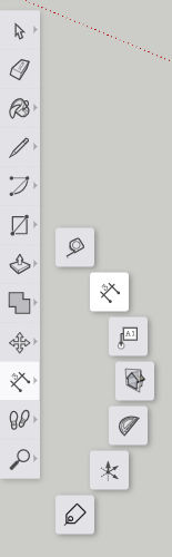
Rotate, stretch, distort, or copy items or objects along a rounded path.
Tool Operation
(Optional) Preselect the items or objects you want to rotate.
Click on an item or object to both make a selection and set the center point of rotation.
Move cursor to indicate start point of rotation.
Click to set starting point of rotation.
Move cursor to indicate end point of rotation.
Click to complete rotation, or enter angle in degrees.
Modifier Keys
Ctrl = Toggle rotate a copy.
Before first click, hold Shift to lock protractor inference.
Before first click, use arrow keys to toggle the protractor inference lock direction (→ = Red, ← = Green, ↑ = Blue, ↓ = Parallel).
After first click, use arrow keys to toggle rotation inference lock direction (→ = Red, ← = Green, ↑ = Blue, ↓ = Parallel/Perpendicular).
Tips
Esc = Cancel operation.
During Step #2 of the tool operation steps above, you can click-drag the protractor along an edge or axis to set an axis of rotation.
After rotating a copy, you can type a number followed by the letter X and then press Enter to create a rotated array of copies.
When inputting rotation values into the Measurements box, you can enter either an angle of rotation, in degrees (for example 45 Enter),or a slope expressed as a rise:run architectural slope notation (for example 4:12 Enter).
(Optional) Preselect the items or objects you want to scale.
Click on a face or object.
Click on a Scale grip.
Move cursor to resize or stretch item or object.
Click to finish scaling item or object.
Modifier Keys
Ctrl = Toggle scale about center.
Shift = Toggle uniform scale.
Tips
Esc = Cancel operation.
Click a corner grip for 3-way scale. Default = Uniform. Pressing Shift = Non-uniform.
Click a midline grip for 2-way scale. Default = Non-uniform. Pressing Shift = Uniform.
Click a center grip for 1-way scale. Default = Non-uniform. Pressing Shift = Uniform.
When scaling an item or object you have the option to enter either a scale factor (for example 2.5 Enter will make the things you’re scaling 250%, or two and a half times bigger), or you can simply input the size that you want the thing you’re scaling to be (for example, if scaling up along the blue axis direction, 6' Enter will make the selection six feet tall).
It’s possible to activate multiple section planes at the same time, as long as the section planes are in different contexts. For example, you can activate one section plane through the model, and then activate another section plane through a group or component object and have both planes active at the same time.
Measure angles and create angled guide line entities.
Tool Operation
Place protractor’s center at vertex of angle.
Click to set vertex. (Alternatively: click and drag first point to set rotation plane.)
Move cursor in circle until touching start of angle.
Click to set start of angle.
Move cursor in circle until touching end of angle.
Click to measure angle.
Modifier Keys
Ctrl = Toggle create guide lines.
Before first click, hold Shift to lock protractor inference.
Before first click, use arrow keys to toggle the protractor inference lock direction (→ = Red, ← = Green, ↑ = Blue, ↓ = Parallel).
After first click, use arrow keys to toggle rotation inference lock direction (→ = Red, ← = Green, ↑ = Blue, ↓ = Parallel/Perpendicular).
Tips
Esc = Cancel operation.
When inputting rotation values into the Measurements box, you can enter either an angle of rotation, in degrees (for example 45 Enter ), or a slope expressed as a rise:run architectural slope notation (for example 4:12 Enter).
Click anywhere in the model to place the camera. The camera will be positioned above the point where you click, at the eye height distance specified in the measurements box.
(Optional) Click and drag from one point in the model to another point in the model to create a target camera. The point you drag from will be the exact location where the camera will be positioned, the point you drag to will establish the camera target.
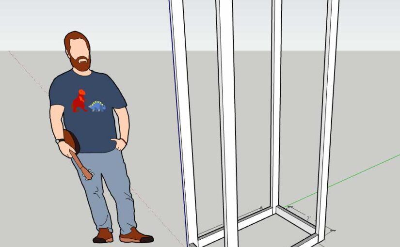
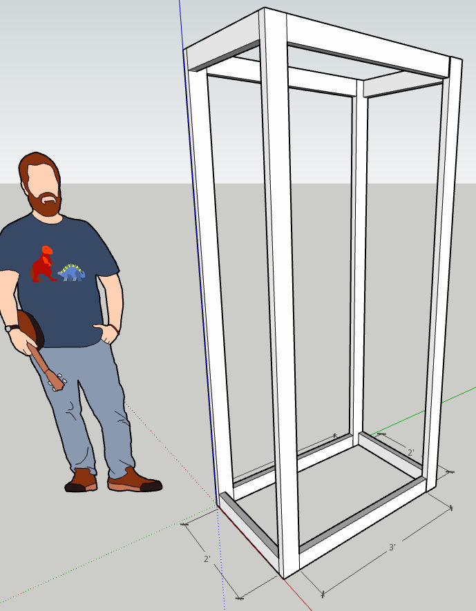
Let’s say you want to make a closet in your garage and you want to create the frame using 2×4 lumber. It’s helpful to draw this in 3D to visualize the design. This post will show you how to do it using the free web version of SketchUp.
Set length units and precision
First, under Model Info, we set the length format and precision. Since a 2×4 piece of wood is actually 1.5″ x 3.5″, let’s set the length and precision to 1/2″.
Create 2×4 objects that represent stock lumber
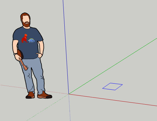
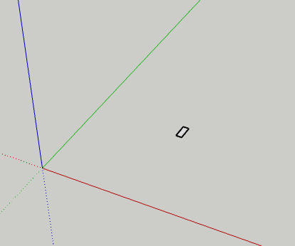
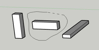
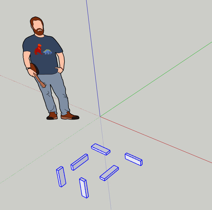
To simplify creating the closet frame out of 2x4s in 3D, we’ll first create 2×4 objects that are any length, e.g. 12 inches long, along each axis (x, y, and z). To do this, we’ll first create a 2×4 rectangle as follows:
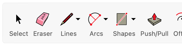
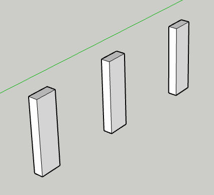
Choose the rectangle tool.
Click and drag anywhere until you see a rectangle.
Before clicking a second time, type “1.5,3.5” (without quotes) to manually specify the dimensions and then hit Enter. What you type will show up in the Dimensions field in the bottom right corner.
You will see the rectangle as shown below.
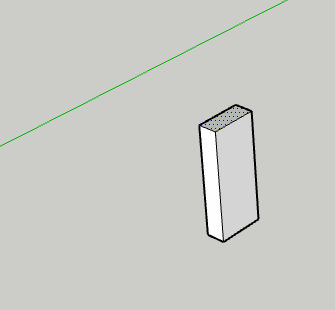
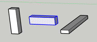
Now, we want to pull the rectangle to create a 12-inch long object representing a piece of wood. Click the Push / Pull tool.
Zoom in, if necessary. Then, click on the face of the rectangle and drag up. Do not click as doing so will set the length. Instead, type “12” (without quotes) to specify the length in inches to pull the rectangle to create a 12″ long 2×4. Then, hit Enter.
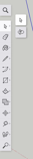
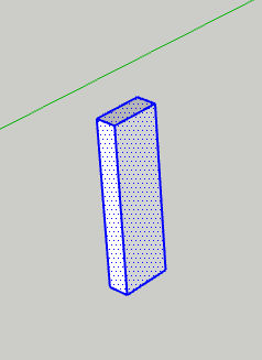
Now that we have one piece of 2×4 in one direction. Let’s copy and paste it twice to create two more pieces in the other two directions. Click the “Select” tool.
Drag a rectangle around the entire object you just created to select all of it. The object will turn blue as shown below.
Click Copy / Ctrl+C and then Paste / Ctrl+V to paste a clone of that object. Do this twice.
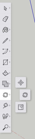
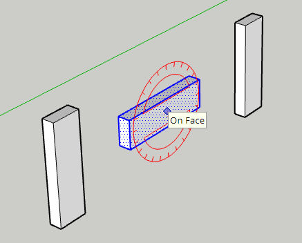
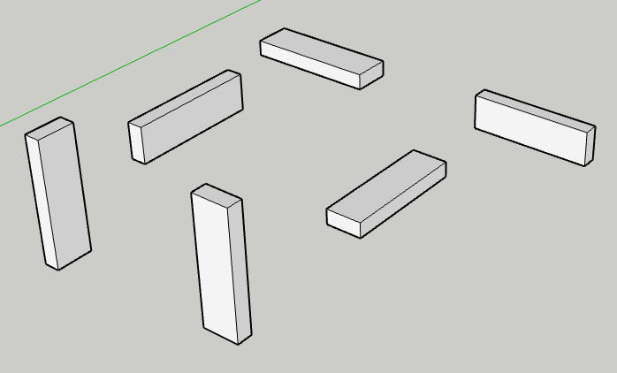
Now, select the 2nd object and then click the Rotate tool.
Click somewhere on the object and then click again to start rotating the object. Don’t click a third time since doing so would set the rotation angle. Instead, type “90” (without quotes) to rotate the object by 90 degrees.
Do the same with the 3rd copy of the object but rotate it in a different direction.
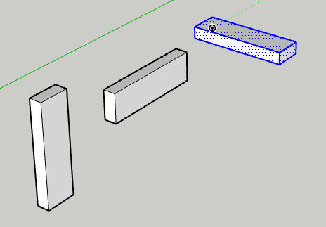
Come to think of it, we should make 3 more copies of the object and rotate them so we can have 2x4s in all 6 perpendicular directions. If you’re having a hard time selecting one entire object using the “Select” tool because it’s too close to another object, try using the “Lasso” selection tool.
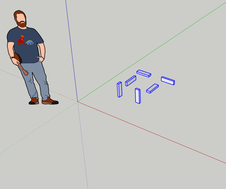
Now we’ve got our 2×4 building blocks which we can move to the side and clone to create the closet frame. I’ll select all 6 objects and move them as shown below.
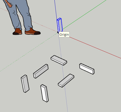
Now, we’ll create a closet frame by first cloning one of the building blocks, moving the clone, and pulling it to change its length. I’ll start with the back left corner of the closet frame. When I copied and pasted one of the 2×4 objects, I clicked on the origin to position the object there.
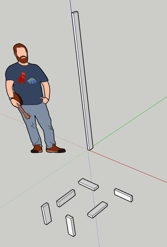
Let’s say we want our closet frame to be 80 inches tall. I’ll switch to the Push / Pull tool, click on the face of the object that I want to pull, drag up, and then type 80 to set the length to 80 inches.
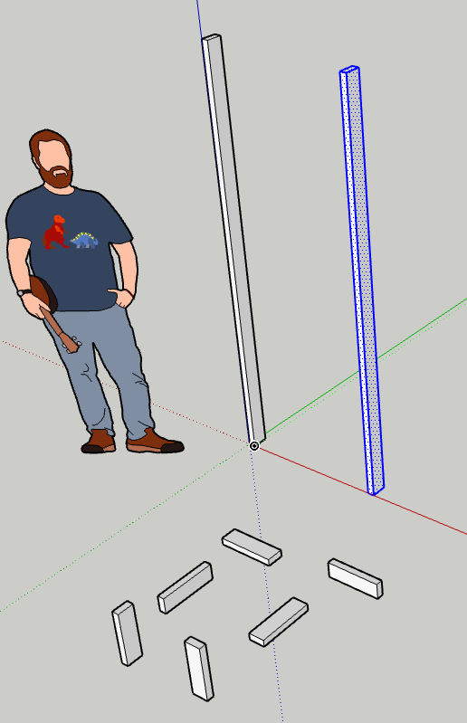
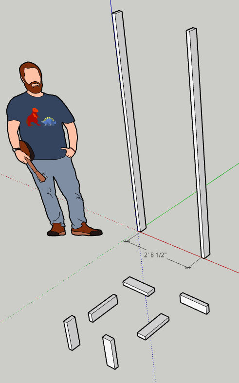
Since we want all corners to be 80 inches tall, we can clone the first 80-inch tall object three more times and position them as far as we want from each other. When you paste a copy of an object, you will see tooltips that help you align the object relative to the axes and to other objects.
Above, we see a copy of the 80-inch tall 2×4 but we don’t know how far it is from the first 80-inch 2×4. Click the Dimensions tool.
Then, click on each of the two endpoints of the distance you want to measure. In this example, the distance is 2′ 8.5″.
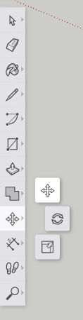
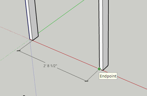
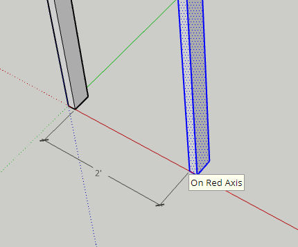
Let’s select the 2nd object and then click the Move tool so we can move the object to be 2 feet away from the other object.
Click on one corner / endpoint and then drag such that the distance becomes 2 feet.
When dragging, you’ll see tips such as “On Red Axis” which will help you stay on the same plane and only move in one direction. Below, we now see the distance between both objects is 2 feet.
Repeat the above steps for the remaining parts.
To learn more, including how to move and align objects relatively and absolutely, read my other SketchUp article.
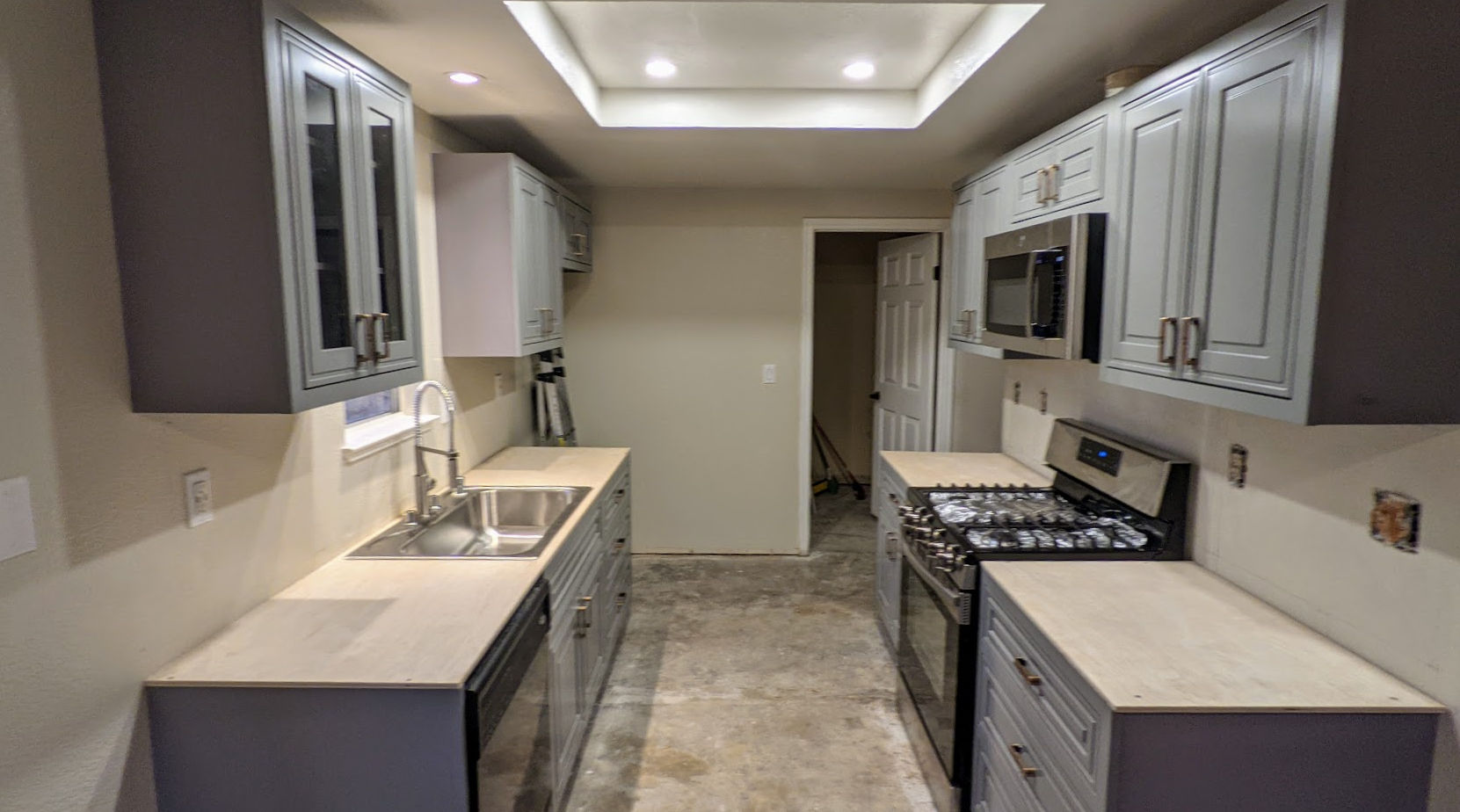
So, last week I renovated one of my rental properties. This included replacing an old kitchen from 1995 with a new one. Here’s an overview of the process.
1. Take a picture of and measure the old kitchen cabinets
I just drew the measurements in Photoshop. Note that the picture below is what the cabinets looked like in 2008. The remodel was done in 2021 and the cabinets were is much worse condition then.
2. Design and order new cabinets
Cabinet Prices
Cabinet prices can vary widely. Home Depot, for example, is expensive. HD Supply has cheap cabinets but they look cheap. IKEA’s cabinets are mid-priced but you have assemble them. Chinese stores have cheap cabinets that look expensive. They also come pre-assembled. But, you have to inspect each cabinet before installing them because their quality control isn’t very good.
Cabinet or Drawers
There are base cabinets that sit on the floor and wall cabinets that are on the wall. Wall cabinets are always just cabinets with a swing out door. They are more expensive if the door has a glass window in it. Base cabinets can be regular cabinets or have drawers. If they are just cabinets, then you’d have a hard time reaching for items in the back of them. If they are drawers, then you can just slide out the drawers to access anything in them. Since drawers require more material and come with sliding mechanisms, they are more expensive then drawers.
Types of Cabinets
2D / 3D Design
I ended up just buying the cabinets from a Chinese store (warehouse) called Uni Tile & Marble.
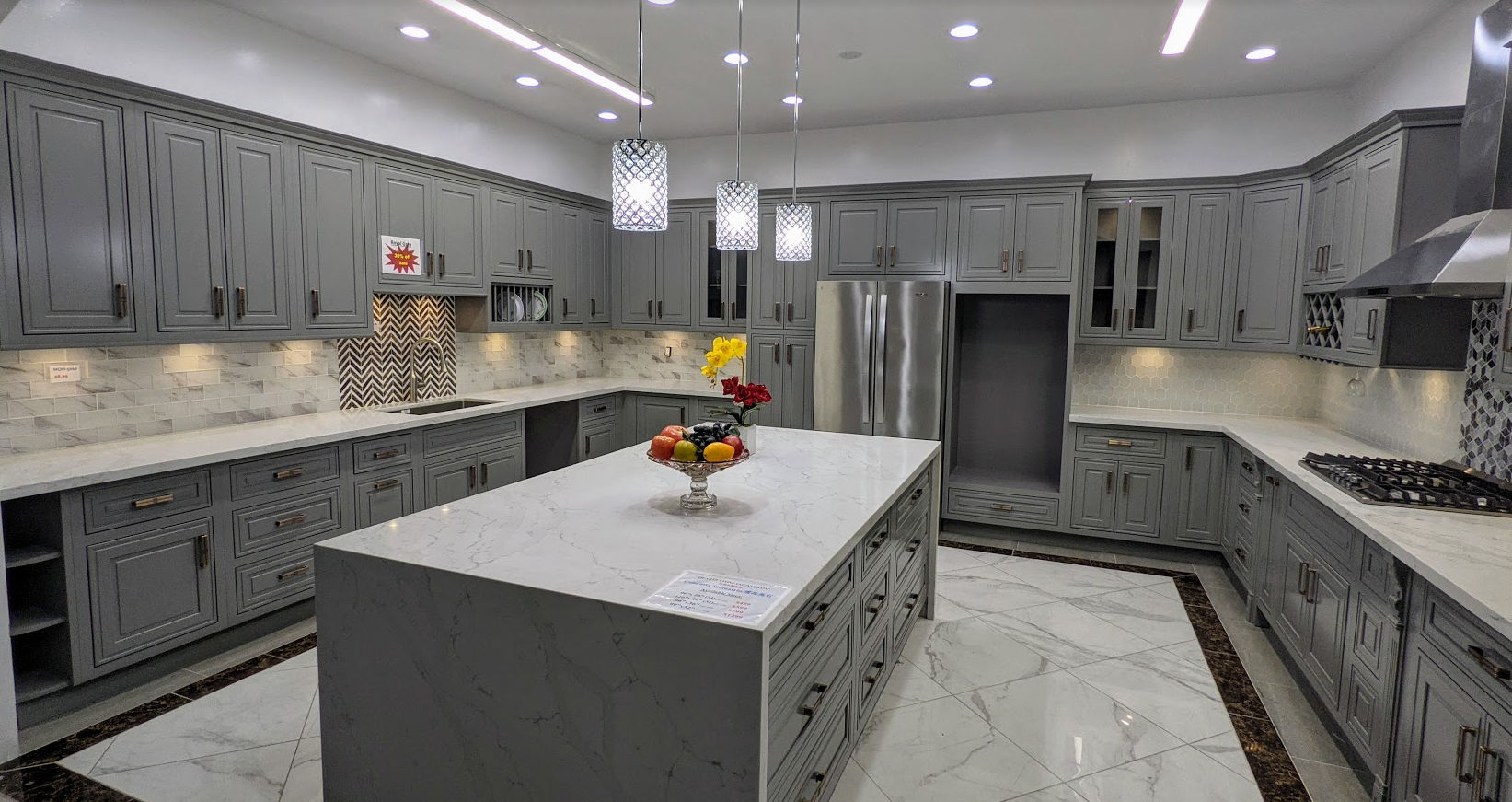
I ended up choosing solid gray color cabinets. This is because the house is a rental house and tenants somehow ruin the surface of the cabinets, I can later just easily repaint the cabinets. This is what the cabinets look like in the showroom.
Countertops
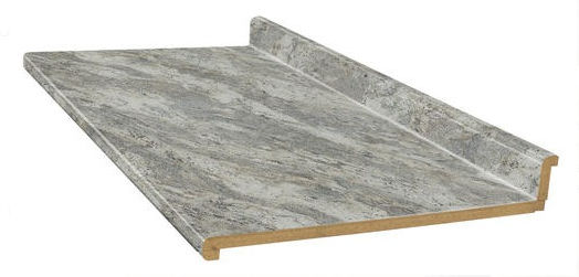
For the countertop, the one on display was off white with a random gray design.
It contrasted well with the gray cabinets and looked exotic but it was also more expensive than other countertops on offer. I decided to go with a cheaper countertop ($300 per 8 foot slab) but my tenant offered to pay the difference for the more expensive countertop so I ended up getting the more expensive one.
Quarts countertops are super heavy and require special handling and are not easy to cut. I ended up paying the store to transport and install the countertops. If you’re looking for a cheaper DIY option, you can just buy cheap laminate countertops at the Home Depot and use a simple jigsaw to cut out the sink hole.
Sinks
For the sink, I prefer the large single basin type. Even though they’re available at Chinese stores, Chinese stores then to have outdated return policies with unreasonable restocking fees (25%) so for these types of items, I buy them at the Home Depot or Lowes.
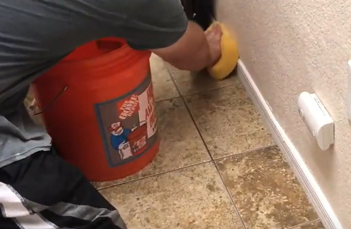
Faucet
For the faucet, I definitely prefer the type in the picture below. It makes it easier to spray and clean the entire sink or whatever else you are washing / cleaning.
3. Pick Up New Cabinets
I could have had the cabinets delivered for a ridiculous $200 fee but since I need to dispose of the old cabinets, I decided to rent a 10′ U-Haul box truck to both pick up the new cabinets and transport the old cabinets to the dump.
A 10′ box truck was big enough to lay all cabinets on the truck bed.
The house were the cabinets will be installed.
4. Demolish Old Cabinets
The old cabinets were original to the house from 1995. They were definitely low quality cabinets. They were just screwed into the wall. Some sections were large so I used a Milwaukee Monster sawzall to cut cabinets in half.
5. Dispose of Old Cabinets
Since we had the truck for 24 hours, we loaded the old cabinets and other construction debris in it
and took it to the dump where I paid $138 to dump it all.
6. Prepare Wall
After removing the kitchen cabinets, the walls needed to be patched up and painted.
First, we enlarged some of the holes in the wall by cutting with an oscillating tool. The holes were shaped like rectangles where vertical edges would be along the center of studs. This would allow us to screw drywall nails through them into the studs. Cutting drywall was easy using a small, cordless reciprocating saw.
We then patched crevices with spackling paste.
After waiting for the spackling paste to dry, I then used an orbital sander to smoothen the wall surface.
I then sprayed wall texture to try to match the texture of the existing wall. This didn’t work well as the material was often clogging up. Next time, just use an air compressor with an actual texture sprayer gun.
I then painted the ceiling Swiss Coffee.
And painted the walls Roman Plaster.
I then touched up the corners where the two colors met. Semigloss paint was used to make cleaning easier.
7. Mark Walls
After the paint dried, we marked where all the studs in the wall were using a stud finder and then marked level (horizontal) and plumb (vertical) points using a laser level.
Then, we connected the points and drew outlines for where the cabinets would go. Note that the distance between the countertop to the bottom of the wall cabinets should be 18 inches.
8. Install Cabinets
We then installed the wall cabinets first. To facilitate this, we screwed a 2×4 to the wall so we could sit the cabinets on it while we screw the cabinets into the wall. If a cabinet didn’t span 2 studs, we’d use drywall anchors.
If walls or floor are not level or flat, use shims.
9. Install Cabinet Handles
To facilitate installing the cabinet handles perfectly, we bought a plastic template / jig. It did not work for drawers, though, so for drawers, we made our own jig.
10. Install Microwave
Since the microwave goes above the range, we installed that next. This required cutting holes in the cabinet above it for bolts and the vent.
11. Install Plywood on Base Cabinets
We then cut plywood and screwed it to the base cabinets.
12. Install Sink
We then cut a hole in the plywood for the sink using a mini circular saw for the straight sides and a jig saw for the corners. Then we installed the faucet, soap dispenser, dishwasher air gap, and garbage disposer to the sink and then installed the sink. This was done before installing the countertop because the countertop would not be ready for another 2 weeks.
I just got a top mount sink that includes the faucet holes rather than an undermount sink. This simplified installation.
13. Install Crown Molding
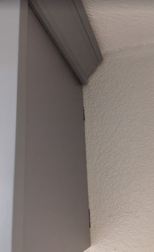
We then installed the crown molding. This was very tricky for a couple of reasons.
depending on the shape of the top of your wall cabinets and the shape of your crown molding, there may not be enough surface area to shoot finish nails into or there may not be enough clearance to shoot nails from above
cutting miter angles can be tricky and holding the crown molding down on the miter saw the same way isn’t easy.
Cutting the crown molding
Fortunately for this project, we only needed 45 degree cuts. But, we messed up a few times at first and wasted some expensive molding. Here are some tips to cut crown molding easily and correctly each time.
Label the surface of the miter saw “TOP” to remind yourself that the top of the crown molding should be facing down and the bottom of the molding flat against the fence.
Find a way to secure 2 pieces of wood to the sides of the miter saw.
Place your crown molding against the fence and then screw a piece of plywood or wood board to the two pieces of wood on each side of the miter saw. This allow you to put the crown molding on the saw at the same angle every time ensuring perfect cuts.
Installing the crown molding
For our particular case, we decided to secure the crown molding to thin plywood using small screws. We then lifted it and let it sit on top of the wall cabinets – no further screwing or nailing necessary.
14. Install Baseboard and Trim Molding
We then cut the baseboard and trim molding to length and shot them into the cabinets using a finish nailer powered by an air compressor. The baseboard and molding were necessary to hide gaps between the cabinets and the floor and walls.
15. Install The Countertop
For the countertops, I decided to go with quartz instead of marble. Since it’s very heavy and tricky to cut and to smoothen the edges, I decided to just pay someone to install the countertops.
First, one of the 8 foot slabs was cut to go on each side of the range. I believe this was done using a diamond blade.
A thin strip of the excess material was cut to make a finished end. The strip was secured using a special epoxy glue.
The strip was then clamped down and the epoxy left to cure for a while.
The installer intentionally cut the slab and the thin strip to be longer than the final length so that after the strip was secured he could cut and trim the end where you see all the glue oozing out.
This resulted in a very clean joint. He then smoothened the end.
This is how the joint ended up looking (with some dust that would eventually be wiped off).
For the sink side, a hole was cut out.
To create rounded corners, the installer cut a bunch of lines at each corner.
And then using a flathead screwdriver, broke off the thin pieces.
And then used an angle grinder to grind away rough edges to create a smooth rounded corner.
They then glued the quartz countertop to the plywood.
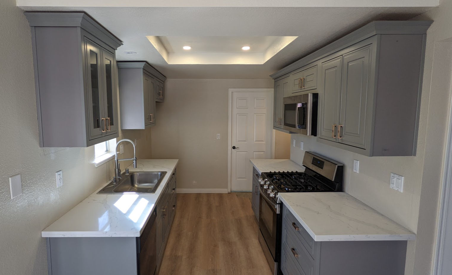
And this is the end result.
Note that we also
replaced the flourescent tube light box with flat LED lights
painted the walls BEHR Roman Plaster (semigloss)
replaced the old style kitchen outlets and switches with new Decora ones including adding a dimmer for the very bright LED lights
replaced the linoleum sheet / vinyl tile flooring with LifeProof Dusk Cherry luxury vinyl planks.
Tools
This project was big enough that I ended up bringing most of my tools to the worksite.
If you have an electrical outlet or switch that isn’t working, here are some steps for debugging and fixing the issue. First of all, it’s important to understand the flow of electricity within a typical home.
Electrical Components and Electricity Flow
Electricity comes through a cable from your local utility to your house
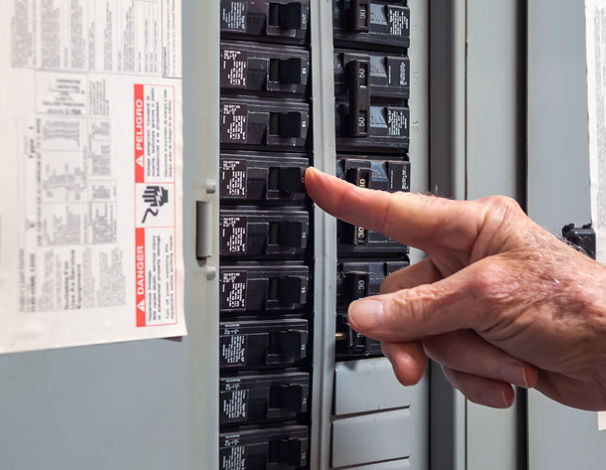
That cable enters a circuit breaker panel on a wall
The circuit breaker panel contains many circuit breakers.
Each circuit breaker has electrical wiring to different parts of the house (kitchen, bedrooms, living room, bathroom, garage, etc). For example, below is a picture of electrical wiring from one circuit breaker in the panel going to 4 outlets. The wiring (or circuit) forms a loop. Electricity flows
from the panel
through the circuit breaker
through the black (hot) wire
through each outlet
through the white (neutral / return) wire
through each outlet
and back to the circuit breaker panel
The bare copper or green wire (ground) goes from each outlet to the circuit breaker panel and then to a rod stuck in the ground.
Each circuit delivers 120 V (volts) of electricity or 240 V depending on the use. Most circuits carry 120 V but electric ranges, electric water heaters and electric clothes dryers carry 240 V since they require more power to function.
Each circuit breaker is rated for a specific number of amperes (amps). Usually 20 A for circuits that require more power, e.g. kitchens, and 15 A for circuits that don’t require much power, e.g. bedrooms.
Circuits that require more power (e.g. 20 Amps vs 15 Amps) use thicker electrical wiring. The smaller the gauge number, the thicker the wire.
12 gauge Romex is rated for 20 Amps and is commonly yellow jacketed.
14 gauge Romex is still used in some applications and is rated for 15 Amps and is grey jacketed.
10 gauge Romex has an orange jacket and is used for water heaters or clothes driers.
The power (P) available to any particular circuit is determined by the voltage (V) running through it and the amps (A) the circuit breaker and the wiring support. The formula for power is P = VxI. So, if a circuit has 120 V and is rated for 15 A, then it supports a maximum power of 120 x 15 = 1800 Watts.
Each device (toaster, laptop, lamp, refrigerator, TV, etc) plugged into an outlet or is in a circuit draws power. The device will indicate how many amps it draws or power (in watts) is consumes to work. For example, below is a label on the back of a toaster oven. It requires 120V AC (alternating current, as opposed to DC, direct current) and it consumes up to 1200 W of power.
This toaster, which consumes up to 1200 W, can be used on a 15 A circuit because a 15 A circuit supports up to 1800 W of power. However, if two of these toasters were plugged in to the came 15 A circuit, then they’d both consume up to 1200 + 1200 = 2400 W which exceeds the power rating of the circuit. This would cause the circuit breaker associated with the circuit to trip and disconnect power to the circuit. Without the circuit breaker, the 15 A rated wiring would begin to melt due to the heat buildup and possibly catch on fire. If the circuit breaker turns off, you can toggle it back on.
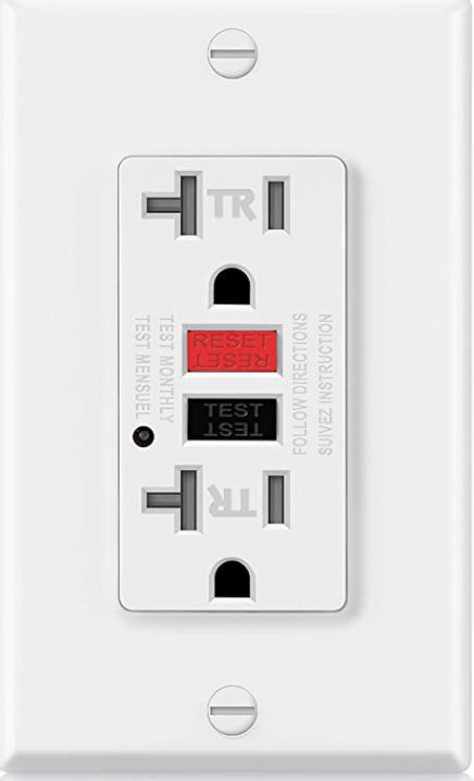
In the picture above, the first outlet is a GFCI (ground fault circuit interrupter) outlet. It behaves like a circuit breaker. If the total power drawn through the outlet exceeds its rating, e.g. 15 A or 20 A, then the outlet would disconnect itself from the circuit thereby rendering the entire circuit without power because it is the first device in the circuit. If a GFCI outlet turns off, you can push a button on it to reset it.
Debugging Electrical Outlets / Switches
Now that we understand basic home electricity, we can make a list of things to check for debugging a non-working outlet or switch or entire circuit.
Outlet not working
Check all circuit breakers in the circuit breaker panel. If any are off, turn them on.
If the outlet is a GFCI outlet, it may have been turned off. Push the RESET button on it to turn it on.
Check neighboring outlets to see if they are working or not as they may be on the same circuit as the outlet that isn’t working. If the neighboring outlets are not working, see if any are GFCI outlets. If any are, then push the RESET button to turn them on. A GFCI outlet that is off will cause downstream devices (outlets, switches, etc) to also be off.
Using a voltage tester tool, test for the presence of voltage at each component (outlet, switch, circuit breaker). Some voltage testers will beep and/or show a red color when it detects voltage.
Try to determine which components (outlets, switches) are on a circuit and in what order.
Plug an outlet tester into the outlet to check whether the wires were installed correctly. For example, the outlet may have an open neutral meaning the white wire may be disconnected. Even if the black (hot) wire is connected, if the white (neutral) wire is disconnected, then the outlet, and all downstream outlets, won’t work. Using an outlet tester is the easiest way to test continuity in wires.
If an open neutral exists, open the outlet and verify the white wire is installed correctly. If the outlet tester still reports an open neutral, then the white wire may be loose or disconnected on the other end, e.g. at the circuit breaker. If the white wire is connected at the circuit breaker, then it could be disconnected somewhere in between both end points, which could happen if a rat chewed on the wire. In that case, new wiring needs to be added.
If the outlet tester reports an open ground (ground wire not connected), then the outlet will still work but it’s not safe to use.
Use the outlet tester on ALL outlets in a circuit. A disconnect in one outlet can cause all downstream outlets to not work.
In order for an outlet to work, electricity must flow from the black wire into the outlet and out from the white wire thereby creating a loop. The outlet tester is one way to check for continuity. Another is by using a multimeter. A multimeter can also be used to trace wires through walls to see to find each end point.
If an outlet sort of works, e.g. a light connected to it is dim or flickers, it could be because there are too many devices drawing too much power to it or the voltage in the circuit is too low, e.g. 85 V instead of 120 V. To determine the actual voltage on the line, you can use a multimeter.
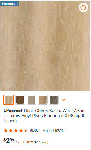
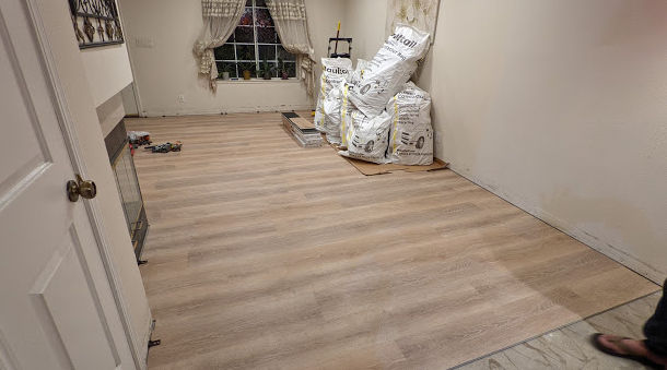
So, I was going to replace the old bamboo flooring in the living room and vinyl tiles on top of linoleum sheet flooring in the dining and kitchen areas of my rental with tile but since I hate dealing with mortar and cutting tile, I asked some contractors to do it. Apparently they all want thousands of dollars so I decided to instead install luxury vinyl planks which are easy enough to do myself (or with a helper). I decided to go with this particular brand and color:
Lifeproof Dusk Cherry 8.7 in. W x 47.6 in. L Luxury Vinyl Plank Flooring
It’s exclusive to the Home Depot and it looks pretty nice. It costs $2.99 per square foot but it comes with the underlayment pre-attached which greatly simplifies installation.
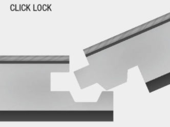
These planks are waterproof and float on the subfloor. No glue or mortar is necessary. The planks click and lock into each other.
Following are some tips I came up with after following the instructions and realizing the instructions could be better.
Subfloor preparation
Removing linoleum sheet / vinyl tile and adhesive
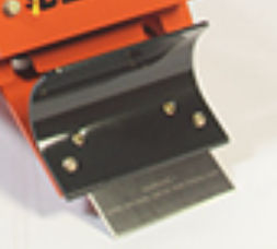
Don’t try to do this by hand. Spend a little bit of money ($85) and rent a power floor scraper. You’ll save a ton of time and energy.
Notice how the top part of the blade sits underneath the black curved deflector. This was problematic because vinyl tiles that were getting stuck where those two parts meet making it difficult to move forward.
To fix this, I unscrewed the bolts and put the scraper blade above the deflector.
This tool is loud and heavy and can’t reach into tight spaces. For tight spaces, I bought a pneumatic floor scraper from Harbor Freight.
This tool requires a compressor that preferably has a large tank. I have a small 2.5 gallon compressor and this tool would work very well at high pressure for about 30 seconds before losing strength. I’d have to stop for another 20 seconds for the compressor tank to fill up before proceeding again with high pressure. To address this, you can buy or rent a large air compressor.
Removing tile flooring and mortar
If you have a lot of tile to remove, you can rent a demolition hammer with the following scraper / breaker attachments.
Installing click-lock vinyl plank flooring
Cutting planks
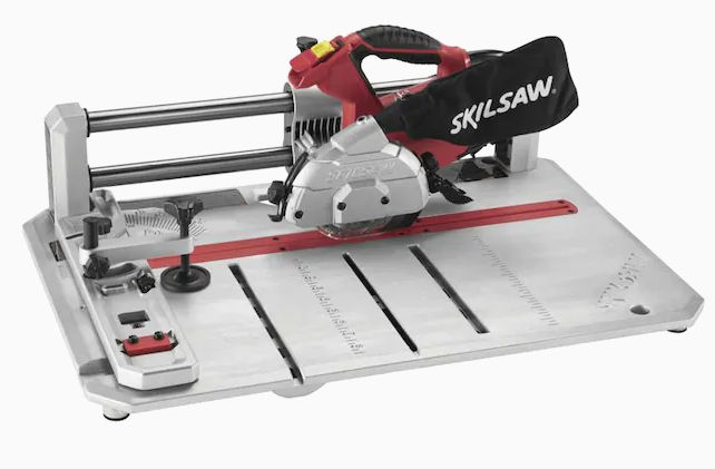
The instructions say to use a utility knife to score planks on both sides and snapping them into two pieces. Though that works without producing any vinyl dust, doing this a lot can get tiring very quickly and is error prone. Instead, just buy a flooring saw like the SKIL 4-3/8-in 7-Amp Sliding Corded Miter Saw.
It’s lightweight and can do rip and cross cuts.
For clean cuts, place the plank face side down and underlayment side up.
If you need to cut irregular shapes or cuts that are difficult with a flooring saw, just use an angle grinder if the cuts don’t need to be perfect since they’ll be hidden underneath baseboard. I temporarily took off the blade guard so I could see where I was cutting.
Spacers
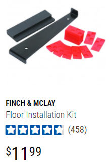
You’re supposed to leave a 1/4 inch gap between the wall and the planks. At first I used the spacers that came with a flooring kit from Harbor Freight.
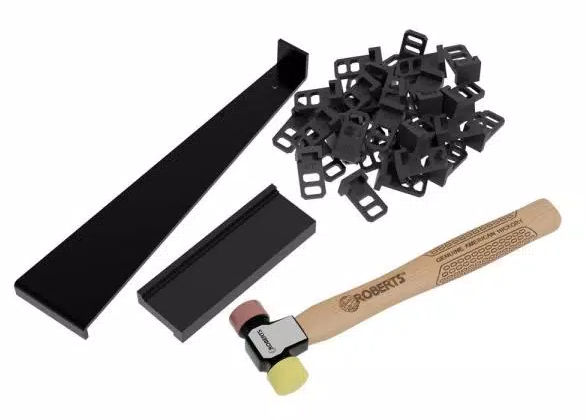
Though this kit is cheap, the spacers and the tapping block are no good. The red spacers keep falling out of place and the tapping block is made of rubber which helps protect the vinyl planks from damage but it makes it difficult to tap the planks together. Instead, by the following tapping block and spacers. Or, just buy the kit which comes with 2 other tools.
Pro Flooring Installation Kit for Vinyl, Laminate and Hardwood Flooring
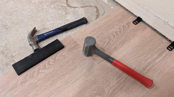
The hammer doubles has a hard side for hitting the tapping black and a soft (mallet) side for hitting vinyl plank seams. Since I did not have this kit, I used a separate hammer and mallet.
Installation Steps
First Row Starting at one end, place a spacer against the wall and lay planks down to lay the first row. Overlay the short end of the planks and tap them together using a mallet.
Second and Even Number Rows Cut a plank in half or at least 8 inches from one end to stagger the placement of planks. Make sure that no plank pieces are less than 8 inches long, if possible.
Install plank by wall Place a spacer by the wall, place a plank such that the long edge overlaps the long edge of the existing plank in the first row at a 45 degree angle.
Then, lay the plank down and tap down on the two long edges using a mallet.
Install next planks The subsequent planks will have two edges that need to be snapped into place – a long edge and a short edge. Again, position the plank at an angle to get the long edge into the groove of the neighboring plank’s long edge. Then, slide the plank towards the short edge of the neighboring plank’s short edge. Lay the plank down and hit the short edge using a mallet.
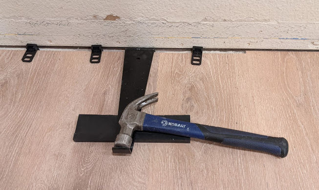
Then, using a hammer, hit the tapping block so there’s no gap between the long edges of the plank.
Keep doing this until you get to the last plank in that row.
Install last plank in row For the last plank in the row, you’ll likely need to cut the plank. Then, install the plank. If you notice any short edges of the planks in that row have a gap, you can close the gap by using the following method. Notice I put the tapping block underneath the metal pull bar which worked better than if you don’t use the tapping block.